Introduction
This article describes the role, usage and version information of AT commands. There are two currently used AT command modes and scenarios, which can be called LOGUART mode and MCU control mode.
Scenario 1: LOGUART Mode
In this mode, users can evaluate the module’s functionality and conduct various tests or demos, such as Wi-Fi or Bluetooth testing.
Note
AT command information will be intermingled with driver logs as both of them will be output from LOGUART.
Scenario 2: MCU Control Mode
This scenario includes connecting the AT command module via UART/SPI/SDIO for rapid product development by the customer. In this mode, AT command information is transmitted and displayed exclusively through UART/SPI/SDIO.
Mode |
Connecting method |
Status |
Scenario |
|---|---|---|---|
LOGUART Mode |
LOGUART |
Ready |
Evaluate/Test/Demo |
MCU Control Mode |
UART |
Ready |
Product development |
SPI |
Developing |
||
SDIO |
Developing |
We set the Ameba module as a slave, and the MCU as a host. The host can send AT commands to the slave and receive the corresponding AT response. Users can use AmebaLite, AmebaSmart, and AmebaDPlus as slaves for AT commands. The AT commands consist of a wide range of types, such as Wi-Fi commands, MQTT commands, TCP/IP commands, and Bluetooth commands.
Hardware Connection
Some hardwares are inquired at first.
LOGUART Mode
Ameba board: As a slave module.
PC (or other host device): Input AT commands, observe the response of AT commands.
LOGUART: Connect the module to PC (or other host device), download image, transmit driver and AT command log.
In case of LOGUART mode, the input and response of AT commands are shown in the same port.

LOGUART mode
MCU Control Mode
Ameba board: As a slave module.
Raspberry Pi (or other MCU host device): Input AT commands, observe the response of AT commands.
LOGUART: Connect module to Raspberry Pi (or other MCU host device), download image, show driver log.
SPI/UART/SDIO: Connect module to Raspberry Pi (or other MCU host device), transmit AT command, show AT command response.
In case of MCU control mode, the input and response of AT commands can be separated from the driver log, making it easier for users to view the execution results of AT commands more intuitively.

MCU Control mode
In MCU Control mode, users should prepare the atcmd_config.json file in advance, convert it into a bin file (refer to Virtual File System for detailed instructions), and download it to the module’s corresponding Flash partition along with the image.
If no VFS AT command configuration file is provided, the default configuration of UART will be used.
For different chips, the default UART input and output ports are listed in the following table.
Chip name |
UART Tx |
UART Rx |
Default baud rate |
|---|---|---|---|
AmebaSmart |
PA_3 |
PA_2 |
38400 |
AmebaLite |
PA_28 |
PA_29 |
38400 |
AmebaDPlus |
PA_26 |
PA_27 |
38400 |
Command Description
Command Format
The current format of the supported AT command set starts with two capital letters AT (abbreviation of attention), called the start characters, followed by a +, then by the command name.
If there are several parameters more, it will be followed by an =, then by a parameter list.
Example
AT+COMMAND=parameter1,parameter2
In this example, the first two letters AT are the start characters, indicating that the current string can be recognized as AT command, and + is used to separate the start characters and subsequent commands.
COMMAND is the specific command name, to be executed right now. This command requires two parameters: parameter1 and parameter2.
Sometimes, several parameters in AT command may be ignored, in this case, one or more comma(s) should be input inside parameters.
Example
AT+COMMAND=parameter1, ,parameter3
In this command, there is an invisible parameter2 between two commas, and it is considered to use the default value.
Command Response
After receiving the AT command, the slave judges whether it is a valid command at first.
If it is considered as an invalid command (not in the AT command set), unkown command COMMAND will be performed.
Otherwise, it will be executed based on the input command and its parameters.
When the command is successfully executed, the command name plus an
OKmark will generally be returned.When the command execution fails, the command name plus an
ERRORmark will generally be returned, followed by an error code.
Note
Every AT command has it’s corresponding error code number and meaning.
Command Parameter
In this section, when introducing the parameter list of an AT command, angle bracket < > is added to indicate the name of the parameter, and square bracket [ ] is added to indicate that the parameter is optional.
Different parameters are separated by commas.
Example
AT+COMMAND=<param1>[,<param2>,<param3>]
In this command, the first parameter named param1 is mandatory, the second parameter named param2, and the third parameter named param3 are optional.
Escapes Character
Especially, in several AT commands, if you really need to let one or more comma(s) be part(s) of a parameter, it is recommended to use escapes character \ instead.
Furthermore, the backslash itself is expressed in escapes character \\.
Example
AT+COMMAND=parameter1,head\,tail,head\\tail
In this command, there are three parameters at all, the second parameter is a string head,tail which includes a comma. The comma inside head,tail will not be considered as a segmentation of parameters, but as a part of a string. And, the third parameter is a string head\tail including a backslash. Single backslash is illegal here, in other words, single backslash must be followed by a comma or another backslash in these AT commands.
For the other AT commands which do not need to use escapes character, the comma will always be considered as a segmentation, and single backslash is allowed as a common character.
AT command |
Parameter(s) with escapes character |
|---|---|
AT+MQTTSUB |
<topic> |
AT+MQTTUNSUB |
<topic> |
AT+MQTTPUB |
<topic>,<msg> |
AT+SKTSEND |
<data> |
Command Length
Each AT command must not exceed a length limit, otherwise, the excess part will be ignored.
There are two types of length limit. When longer command format is enabled, the length limit is 4095 bytes, otherwise (shorter command format), the length limit is 126 bytes.
When the AT command using escapes character, the escapes characters such as \ or \\ should be regarded as 2 bytes.
You can modify the length limit by make menuconfig when compiling the SDK. If you select the option Enable Longer CMD, the length limit will be larger.
AT Command List
The AT commands supported now are listed below.
Please refer to each section to look for more details about the command information of different AT commands.
AT Command Version
Users can query the current firmware’s AT command version by executing AT+GMR command.
The version number employs a semantic versioning system, and its format is as follows:
<major>.<minor>.<patch>
Where:
- <major>:
the major version, represents major updates, typically including the introduction of new chip support, new features, etc.
- <minor>:
the minor version, represents important updates, typically including new commands, bug fixes, etc.
- <patch>:
the patch version, represents fixing some issues without adding any new features.
Example
// send ATCMD
AT+GMR
// receive ATCMD response
+GMR:
ATCMD VERSION: v2.2.1
SDK VERSION: v3.5
Building image
Preparation
Besides obtaining the release version from GitHub, users can also build images with {sdk} by self. For detailed building procedure, refer to the Application Note of the specific Ameba chips.
Building
After preparations above, users can build images in the {sdk} directory. The procedure is as follows:
Run
make menuconfigto choose MCU Control mode or LOGUART mode.// Your SDK direction cd $ {sdk} // The chip type you choose, e.g. amebadplus_gcc_project cd source/{ameba_name} make menuconfig // ...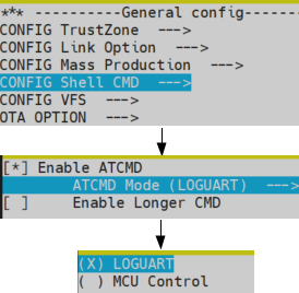
Choice mode
Run
make allto rebuild the project.After building successfully, the image files can be found under
{ameba_name}directory.
If users want to use Bluetooth AT Commands, run $make menuconfig to enable BLE transfer module first.
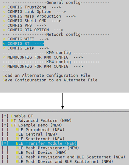
Enable BLE transfer module
Downloading Image
There are two ways to download image to Flash:
Image Tool, a software provided by Realtek (recommended).
GDB Server, mainly used for GDB debug user case.
In this section, we will introduce the first one.
The Image Tool is the official image download tool developed by Realtek for Ameba series SoC. It can be used to download images to the Flash of device through the UART download interface.
When you lanuch the image tool, it is shown as the following figure.
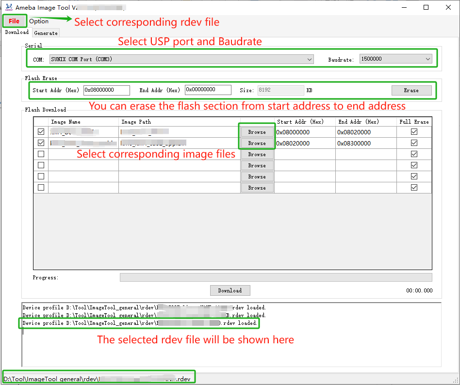
Image Tool
The device profiles provide the necessary device information required for image download, with the naming rules:
<SoC name>_<OS type>_<Flash type>[_<Extra info>].rdev
For different Ameba chips, click the to select the corresponding .rdev file before downloading image to Flash. Then, select the corresponding image files.
Before downloading image, the chip should enter download mode at first.
Press and hold the DOWNLOAD button on chip
Press the CHIP_EN button
Release them both to let the chip enter download mode
Connect the chip module to PC with USB cable, and press the DOWNLOAD button of Image Tool to start downloading the image files