Introduction
There are two-CPUs named KM4 (AP) and KM0 (NP) integrated in the RTL8721Dx. The inter-processor communication (IPC) hardware is designed to make these CPUs communicate with each other. Also, a KM0 shared SRAM is used to transmit information to each other. The block diagram is shown in the following figure.

IPC block diagram
General Principle
There are 2 directions for 2 cores to communicate with each other: KM0 ←→ KM4. There are 16 TX channels and 16 RX channels for each direction. All the channels are processed independently. That means one core can send different information to another core through different channels at any time, the channels will not affect each other.
Each channel has one transmit side and one receive side, the transmit side and the receive side of the same channel is a pair. For example, KM0 sends an IPC to KM4 through channel 7, the transmit side is KM0 channel 7, and receive side is KM4 channel 7, and information is sent from KM0 channel 7 to KM4 channel 7.

IPC schematic diagram
How to Use IPC
IPC Usage Procedure
For example, KM0 sends an IPC to KM4 through channel 8.
Register the receiver IRQ handler function of the selected channel in receiver IPC.
In this case, add a new IPC_INIT_TABLE in the KM4 for channel 8 of KM0 to KM4. Rx IRQ handler, Rx IRQ data, Tx IRQ handler, Tx IRQ data, IPC direction and IPC channel should be set and defined. If message exchange is needed, you should specify the message type: data or point.
1IPC_TABLE_DATA_SECTION
2Const IPC_INIT_TABLE ipc_channel8_table[] = {
3{IPC_USER_DATA, IPC_CHANNEL8_ipc_int, (VOID *)NULL, IPC_TXHandler, (VOID *)NULL , IPC_KM0_TO_KM4, IPC_N2A_Channel8},
4};
Uncomment the corresponding channel in
ameba_ipccfg.hand add some description as shown below. This macro is used in step 5.1/** @defgroup IPC_KM0_Tx_Channel 2* @{ 3*/ 4#define IPC_N2A_TICKLESS_INDICATION 0 /*!< KM0 -> KM4 Tickless indicate */ 5#define IPC_N2A_WAKE_AP 1 /*!< KM0 -> KM4 Wakeup*/ 6#define IPC_N2A_WIFI_FW_INFO 2 /*!< KM0 -> KM4 FW Info*/ 7#define IPC_N2A_FLASHPG_REQ 3 /*!< KM0 -> KM4 Flash Program REQUEST*/ 8#define IPC_N2A_LOGUART_RX_SWITCH 4 /*!< KM0 -> KM4 Loguart Rx Switch*/ 9#define IPC_N2A_BT_API_TRAN 5 /*!< KM0 -> KM4 BT API Exchange */ 10// #define IPC_N2A_BT_DATA_TRAN 5 /*!< KM0 -> KM4 BT DATA Exchange */ 11#define IPC_N2A_WIFI_TRX_TRAN 6 /*!< KM0 -> KM4 WIFI Message Exchange */ 12#define IPC_N2A_WIFI_API_TRAN 7 /*!< KM0 -> KM4 API WIFI Message Exchange */ 13#define IPC_N2A_Channel8 8 14//#define IPC_N2A_Channel9 9 15//#define IPC_N2A_Channel10 10 16//#define IPC_N2A_Channel11 11 17//#define IPC_N2A_Channel12 12 18//#define IPC_N2A_Channel13 13 19//#define IPC_N2A_Channel14 14 20//#define IPC_N2A_Channel15 15 21/** 22* @} 23*/
Register the transmit IRQ handler function of the selected channel in transmit IPC and uncomment the corresponding channel. This step is
optional, because this step is for register Tx interrupt, which is for transmit IPC to know that the receiver IPC has received this IPC. In this case, add a new IPC_INIT_TABLE in the KM0 for channel 8 of KM0 to KM4.
SDK will enable the IPC receiver interrupt of KM4 and transmit interrupt of KM0 (if configured in step 3) according to
IPC_INIT_TABLE, and register the corresponding IRQ handler and data for the channel.
When KM0 sends an IPC request to KM4 through channel 8, it should call
ipc_send_message()and specify the channel number and message. If no message is needed, just input NULL for the third parameter ofipc_send_message ().1IPC_MSG_STRUCT ipc_msg_temp; 2// init ipc_msg 3ipc_msg_temp.msg_type = IPC_USER_POINT; 4ipc_msg_temp.msg = (u32)&tmp_np_log_buf; 5ipc_msg_temp.msg_len = 1; 6ipc_msg_temp.rsvd =0; 7//send ipc message 8ipc_send_message(IPC_KM0_TO_KM4, IPC_N2A_Channel8, & ipc_msg_temp);
After receiving IPC from KM0 channel8, KM4 will enter IPC interrupt handler and the corresponding receive IRQ handler will be executed, call
ipc_get_message()to get the message if needed.PIPC_MSG_STRUCT ipc_msg_temp = (PIPC_MSG_STRUCT)ipc_get_message(IPC_KM0_TO_KM4, IPC_N2A_Channel8);
If you have configured in step 3, after KM4 receives the IPC, KM0 also enters IPC interrupt handler and executes the corresponding transmit IRQ handler.
Note
Several channels are already used by Realtek, you can use the remaining channels.
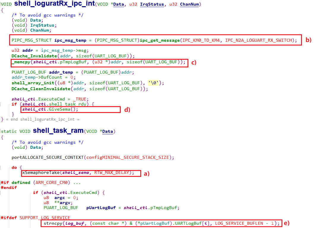
Suggested Usage of ipc_get_message()
Use
ipc_get_message()in IPC interrupt handle or user interrupt handler.1void IPC_CHANNEL8_ipc_int(void *Data, u32 IrqStatus, u32 ChanNum) 2{ 3/* To avoid gcc warnings */ 4(void) Data; 5(void) IrqStatus; 6(void) ChanNum; 7PIPC_MSG_STRUCT ipc_msg_temp = (PIPC_MSG_STRUCT)ipc_get_message(IPC_KM0_TO_KM4, IPC_N2A_Channel8); 8u32 addr = ipc_msg_temp->msg; 9}
1IPC_TABLE_DATA_SECTION
2const IPC_INIT_TABLE ipc_channel8_table[] = {
3{IPC_USER_DATA, IPC_CHANNEL8_ipc_int, (VOID *)NULL, IPC_TXHandler, (VOID *)NULL, IPC_KM0_TO_KM4, IPC_N2A_Channel8},
4};
IPC_MSG_STRUCTis no need to cache invalidation any more afteripc_get_message().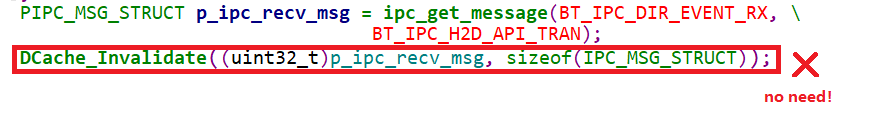
Forcing
IPC_MSG_STRUCTtype conversion has risks.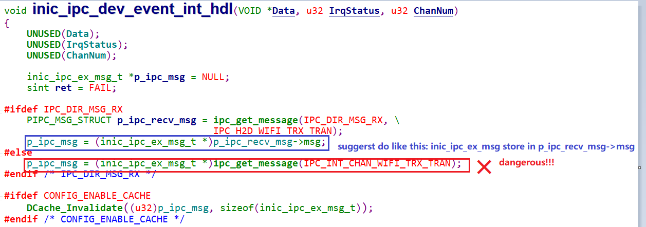
Using
ipc_get_message()in task also has risks.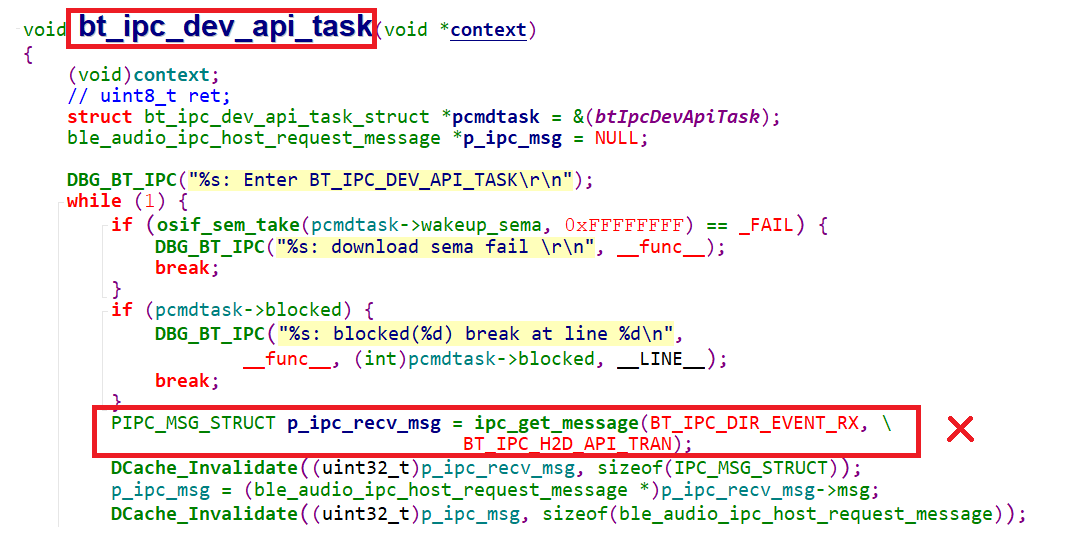
If
ipc_get_message()needs to be used intask, do as follows:Task takes the semaphore.
In IPC Rx user interrupt handle, using
ipc_get_message()to get a message.Copy the message to another memory after getting message in the same Rx user interrupt handle.
Give semaphore.
Then task can use the message.
Troubleshooting
If Channel Conflict for CPU xx Channel xx! log shows up, it means two IRQ functions are registered in the same channel. For example, if IRQFunc1 and IRQFunc2 are both registered in KM4 for KM0 to KM4 channel1, the log will show up as below.
14:23:03.905 [MODULE_IPC-LEVEL_ERROR]: Channel Conflict for CPU 1 Channel1 ! Ignore If CPU Has Reset