电源管理架构
SoC 搭载了先进的电源管理控制器(Power Management Controller,PMC),可灵活控制芯片不同电源域的上电时序,实现性能与功耗的最佳平衡。
SoC 的数字系统中包含三个核心电源域:AON 域、SYSON 域和 SOC 域。不同省电模式下,各电源域的关断策略存在差异。
Ameba 系列 SoC 的电源域和唤醒源如下所示:


低功耗模式
Ameba SoC 支持两种低功耗模式:睡眠(Sleep)模式与深度睡眠(Deep-Sleep)模式。深度睡眠模式比睡眠模式关闭更多电源域,因此功耗更低。
Tickless 是 FreeRTOS 的低功耗功能,当系统空闲时会暂停 CPU(不关闭时钟或电源)。睡眠模式流程和深度睡眠模式流程均基于 Tickless 实现。
下表详细解释了省电相关术语:
模式 |
AON 域 |
SYSON 域 |
SOC 域 |
描述 |
|---|---|---|---|---|
Tickless |
ON |
ON |
ON |
|
Sleep |
ON |
ON |
时钟门控(CG)或电源门控(PG) |
|
Deep-Sleep |
ON |
OFF |
OFF |
|
FreeRTOS Tickless
FreeRTOS 的 Tickless 低功耗特性通过优先级最低的空闲任务实现,即当系统没有其他运行任务时触发。
备注
与原生 FreeRTOS 不同,不依赖 xExpectedIdleTime 进行唤醒。

空闲任务中的 FreeRTOS Tickless
上图展示了空闲任务的代码流程。在空闲任务中,系统会检查睡眠条件(包括唤醒锁状态、系统活跃时间等,详见章节 唤醒锁 API 和 pmu_set_sysactive_time),以决定是否进入睡眠模式。
当条件不满足时:CPU 执行 ARM WFI (等待中断)指令,使处理器挂起直至中断触发。通常由 SysTick 中断恢复运行,此模式称为 软件 Tickless。
当条件满足时:执行函数
freertos_pre_sleep_processing()进入睡眠模式或深度睡眠模式
备注
即使设置了 FreeRTOS 时间控制机制(如软件定时器或 vTaskDelay),只要空闲任务被执行且满足条件,系统仍会进入睡眠模式。
低功耗应用必须启用 configUSE_TICKLESS_IDLE 配置项,因为睡眠模式基于 Tickless 机制实现。
Wi-Fi 低功耗
IEEE 802.11 省电管理允许站点自主进入睡眠状态,其核心规则为:
站点必须在特定时间戳保持唤醒状态,其余时间可进入睡眠状态
WLAN 驱动通过获取唤醒锁(Wakelock)阻止系统在需保持活跃时进入睡眠模式
当允许休眠时,WLAN 驱动释放唤醒锁
站点休眠期间无法接收任何数据帧,因此 AP 需缓存待传数据帧,站点需周期性唤醒检测信标帧。
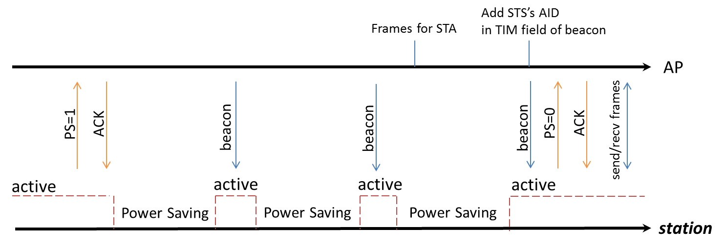
省电模式时序图
SDK中的实现模式如下:
IEEE 802.11 power management is called LPS, and if NP enters sleep mode when Wi-Fi is in LPS mode, we call it WoWLAN mode.
In WoWLAN mode, a timer with a period of about 102ms will be set in the suspend function. And LP will wake up every 102ms to receive the beacon to maintain the connection.
Except for LPS and WoWLAN, we also have IPS, which can be used when Wi-Fi is not connected. The following tables list all three power-saving modes for Wi-Fi and the relationship between the system power mode and Wi-Fi power mode.
模式 |
Wi-Fi 状态 |
描述 |
SDK |
|---|---|---|---|
IPS |
未关联:
|
Wi-Fi 驱动自动关闭 Wi-Fi 模块 |
默认启用 IPS 模式,强烈不建议禁用 |
LPS |
已关联:
|
LPS 模式用于实现 IEEE 802.11 省电管理 NP 基于信标的 TSF 和 TIM IE 控制射频的开关 |
默认启用 LPS 模式,可通过 API
|
WoWLAN |
已关联:
|
NP 在每次信标提前中断时被唤醒,以接收来自关联 AP 的信标帧 当接收到数据包时,NP 将触发 AP 唤醒流程 |
默认启用 WoWLAN 模式 |
系统功耗模式和 Wi-Fi 功耗模式之间的关系如下表所示:
系统功耗模式 |
Wi-Fi 功耗模式 |
描述 |
|---|---|---|
Active |
IPS |
Wi-Fi 已开启但未建立连接 |
LPS |
Wi-Fi 已连接并进入 IEEE 802.11 省电管理模式 |
|
Sleep |
Wi-Fi 关闭/IPS |
|
WoWLAN |
Wi-Fi 保持关联状态 |
|
Deep-Sleep |
Wi-Fi 关闭 |
需保持 Wi-Fi 持续在线或关联的场景,不推荐使用 Deep-Sleep 模式 |
启用/禁用 LPS 的 API 如下:
int wifi_set_lps_enable(u8 enable);
参数说明:
- TRUE:
启用 LPS
- FALSE:
禁用 LPS
当 Wi-Fi 已连接且系统进入睡眠模式时,将周期性进入 WoWLAN 模式。此模式下,KM0 以固定周期唤醒来接收信标帧维持连接,这会导致一定的功耗。
若需进一步降低睡眠模式下的系统功耗,且应用中无须 Wi-Fi 功能,建议关闭 Wi-Fi 模块或者选择 Wi-Fi IPS 模式。
唤醒源
在不同低功耗模式下,可用于唤醒系统的唤醒源如下表所示:
唤醒源 |
Sleep CG |
Sleep PG |
Deep-Sleep |
限制 |
|---|---|---|---|---|
WLAN |
√ |
√ |
X |
|
BT |
√ |
√ |
X |
|
IPC |
√ |
√ |
X |
仅 KM0 可通过 IPC 唤醒 KM4 |
Basic Timer4~7 |
√ |
√ |
X |
|
PMC Timer |
√ |
√ |
X |
仅内部使用 |
UART0~2 |
√ |
√ |
X |
当使用 UART 作为唤醒源时:
|
LOGUART |
√ |
√ |
X |
当使用 LOGUART 作为唤醒源时:
|
GPIO |
√ |
√ |
X |
|
I2C |
√ |
√ |
X |
|
CAP_TOUCH |
√ |
√ |
X |
|
ADC |
√ |
√ |
X |
|
SDIO |
√ |
√ |
X |
|
Key-Scan |
√ |
√ |
X |
|
BOR |
√ |
√ |
√ |
|
PWR_DOWN |
√ |
√ |
√ |
|
AON_TIMER |
√ |
√ |
√ |
|
AON_WAKEPIN |
√ |
√ |
√ |
|
RTC |
√ |
√ |
√ |
A hardware SYSON power management control module (SYSON PMC) is designed to control the clock and power of NP, and then NP controls the clock and power of AP. When the system enters sleep mode, CPUs can select to enter clock-gating (CG) or power-gating (PG) mode, while SYSON PMC maintained active to wake up NP when wakeup sources are triggered.
Sleep and wakeup flow of sleep mode can be described as:
In terms of sleep flow, NP helps close the clock or power of AP and DSP, and SYSON PMC helps close the clock or power of NP.
In terms of wakeup flow, SYSON PMC helps open the clock or power of NP, and NP helps open the power or clock of AP and DSP.
备注
Both KM4 and KR4 can be configured as NP. If KR4 is configured as NP, KM4 is considered as AP.
The mode of memory is configurable when the system enters sleep mode. The retention mode is recommended for the balance between power saving and data retention.
In deep-sleep mode, only the memory in AON domain can be maintained, while memory in other domains will be shut down. So CPU cannot restore the stack status.
Various wakeup sources are provided and every wakeup source can be configured to wake up NP or AP according to user’s requirement. AON is special because it is mater switch that manages all the wake-up sources in AON domain. Only wakeup sources in AON domain can wake up the system from deep-sleep mode.
The following table lists the wakeup sources that can be used to wake up the system under different power modes.
Wakeup source |
Sleep CG |
Sleep PG |
Deep-Sleep |
Restriction |
|---|---|---|---|---|
WLAN |
√ |
√ |
X |
|
BT |
√ |
√ |
X |
|
IWDG |
√ |
√ |
X |
|
IPC |
√ |
√ |
X |
|
Basic Timer |
√ |
√ |
X |
|
UART |
√ |
√ |
X |
|
LOGUART |
√ |
√ |
X |
|
GPIO |
√ |
√ |
X |
|
SPI |
√ |
√ |
X |
|
CAP_TOUCH |
√ |
√ |
X |
|
ADC |
√ |
√ |
X |
|
VAD |
√ |
√ |
X |
|
BOR |
√ |
√ |
√ |
|
PWR_DOWN |
√ |
√ |
√ |
|
AON_TIMER |
√ |
√ |
√ |
|
AON_WAKEPIN |
√ |
√ |
√ |
|
RTC |
√ |
√ |
√ |
A hardware SYSON power management control module (SYSON PMC) is designed to control the clock and power of NP, and then NP controls the clock and power of AP. When the system enters sleep mode, CPUs can select to enter clock-gating (CG) or power-gating (PG) mode, while SYSON PMC maintained active to wake up NP when wakeup sources are triggered.
Sleep and wakeup flow of sleep mode can be described as:
In terms of sleep flow, NP helps close the clock or power of AP, and SYSON PMC helps close the clock or power of NP.
In terms of wakeup flow, SYSON PMC helps open the clock or power of NP, and NP helps open the power or clock of AP.
备注
Both KM4 and KR4 can be configured as NP. If KR4 is configured as NP, KM4 is considered as AP.
The mode of memory is configurable when the system enters sleep mode. The retention mode is recommended for the balance between power saving and data retention.
In deep-sleep mode, only the memory in AON domain can be maintained, while memory in other domains will be shut down. So CPU cannot restore the stack status.
Various wakeup sources are provided and every wakeup source can be configured to wake up NP or AP according to user’s requirement. AON is special because it is mater switch that manages all the wake-up sources in AON domain. Only wakeup sources in AON domain can wake up the system from deep-sleep mode.
The following table lists the wakeup sources that can be used to wake up the system under different power modes.
Wakeup source |
Sleep CG |
Sleep PG |
Deep-Sleep |
Restriction |
|---|---|---|---|---|
WLAN |
√ |
√ |
X |
|
BT |
√ |
√ |
X |
|
IWDG |
√ |
√ |
X |
|
IPC |
√ |
√ |
X |
|
Basic Timer |
√ |
√ |
X |
|
UART |
√ |
√ |
X |
|
LOGUART |
√ |
√ |
X |
|
GPIO |
√ |
√ |
X |
|
SPI |
√ |
√ |
X |
|
CAP_TOUCH |
√ |
√ |
X |
|
ADC |
√ |
√ |
X |
|
VAD |
√ |
√ |
X |
|
BOR |
√ |
√ |
√ |
|
PWR_DOWN |
√ |
√ |
√ |
|
AON_TIMER |
√ |
√ |
√ |
|
AON_WAKEPIN |
√ |
√ |
√ |
|
RTC |
√ |
√ |
√ |
在不同低功耗模式下,可用于唤醒系统的唤醒源如下表所示:
唤醒源 |
Sleep CG |
Sleep PG |
Deep-Sleep |
限制 |
|---|---|---|---|---|
WLAN |
√ |
√ |
X |
|
BT |
√ |
√ |
X |
|
AON_WAKEPIN |
√ |
√ |
√ |
|
UART |
√ |
√ |
X |
当使用 UART 作为唤醒源时:
|
IPC |
√ |
√ |
X |
IPC 只能唤醒 CA32 和 KM4,不能唤醒 KM0 |
SPI |
√ |
X |
X |
|
VAD |
√ |
X |
X |
|
BOR |
√ |
√ |
√ |
|
PWR_DOWN |
√ |
√ |
√ |
|
CAP_TOUCH |
√ |
√ |
X |
|
ADC |
√ |
√ |
X |
|
RTC |
√ |
√ |
√ |
|
GPIO |
√ |
√ |
X |
|
LOGUART |
√ |
√ |
X |
当使用 LOGUART 作为唤醒源时:
|
Basic Timer |
√ |
√ |
X |
|
IWDG |
√ |
√ |
X |
|
AON_TIMER |
√ |
√ |
√ |
SYSON 电源管理控制器(SYSON PMC)用于控制 LP 的时钟和电源,之后 LP 控制 NP 和 AP 的时钟和电源。
当系统进入睡眠时,CPU 可以选择进入 CG 或 PG 模式,此时 SYSON PMC 保持全功能运行,当有唤醒源触发时负责唤醒 LP。
进入 Sleep 模式
睡眠模式基于FreeRTOS Tickless 模式实现,因此推荐通过释放唤醒锁(Wakelock) 的方式进入睡眠模式。
初始化目标外设
启用和注册外设中断
设置
ambea_sleepcfg.c文件中的sleep_wevent_config[],确保中断注册在sleep_wevent_config[]选择的相同的 CPU 上对于需要特殊时钟配置的外设,在
ameba_sleepcfg.c文件中设置ps_config[]根据需要注册睡眠/唤醒回调函数
通过释放 AP 的唤醒锁进入睡眠模式(启动时 PMU_OS 默认被占用,需在进入睡眠模式前释放)
在系统唤醒后,及时清除外设中断
进入 Deep-Sleep 模式
通过 FreeRTOS Tickless 流程同样可以进入深度睡眠模式。
当系统启动时,应用处理器(AP)自动持有深度唤醒锁 PMU_OS,导致 freertos_ready_to_dsleep() 校验失败,系统默认不在空闲任务中进入深度睡眠模式。
只有当 freertos_ready_to_sleep() 校验通过,才会校验 freertos_ready_to_dsleep(),因此需同时释放唤醒锁和深度唤醒锁方可进入深度睡眠模式。
配置:
初始化目标外设并启用中断
在
ameba_sleepcfg.c文件中设置sleep_wakepin_config[],使用 AON 唤醒引脚作为唤醒源通过释放 AP 的唤醒锁和深度唤醒锁进入深度睡眠模式
低功耗配置
Please reference User Config chapter for detail information.
低功耗相关 API
唤醒锁 API
在某些情况下,系统需要保持清醒以接收特定事件,在睡眠模式下可能会错过这些事件。因此,引入了唤醒锁(Wakelock)的概念:如果某个模块持有唤醒锁,系统将无法进入睡眠模式。
唤醒锁是一个 32 位的映射。每个模块在唤醒锁位图中都有其对应的位(参见枚举 PMU_DEVICE)。用户也可以在枚举中添加唤醒锁。
如果唤醒锁位图等于零,表示没有模块持有唤醒锁。
如果唤醒锁位图大于零,表示有模块正持有唤醒锁,系统不允许进入睡眠模式。
Wakelock is a judging condition in the function freertos_ready_to_sleep().
When the system boots, application core(AP) holds the wakelock PMU_OS, and network core(NP) holds the wakelock PMU_OS and PMU_KM4_RUN or PMU_AP_RUN.
Only if all wakelocks are released, AP or NP is permitted to enter sleep mode. The function freertos_ready_to_sleep() will judge the value of wakelock.
enum PMU_DEVICE {
   PMU_OS        = 0,
   PMU_WLAN_DEVICE,
   PMU_KM4_RUN,
   PMU_WLAN_FW_DEVICE,
   PMU_BT_DEVICE,
   PMU_DEV_USER_BASE,
   PMU_MAX
};
It is recommended to enter sleep mode by releasing the wakelock. After the wakelock PMU_OS of AP is released, AP will enter sleep mode in idle task and send IPC to NP. NP will power-gate or clock-gate AP and then release PMU_OS and PMU_KM4_RUN or PMU_AP_RUN.
When the system wakes, it will enter sleep mode again quickly unless it acquires the wakelock.
Similar to the wakelock for sleep mode, there is a 32-bit deepwakelock map for deep-sleep mode. If the deepwakelock bit map is larger than zero, it means that some modules are holding the deepwakelock, and the system is not allowed to enter deep-sleep mode. When the system boots, application core holds the deepwakelock PMU_OS.
Deepwakelock is a judging condition in the function freertos_ready_to_dsleep().
After the deepwakelock PMU_OS of AP is released, and all wakelocks of AP are released, AP will be allowed to enter deep-sleep mode and send IPC to NP in idle task.
NP will send a deep-sleep request and let the chip finally enter deep-sleep mode.
Wakelock is a judging condition in the function freertos_ready_to_sleep().
When the system boots, application core(AP) holds the wakelock PMU_OS, and network core(NP) holds the wakelock PMU_OS and PMU_KM4_RUN or PMU_AP_RUN.
Only if all wakelocks are released, AP or NP is permitted to enter sleep mode. The function freertos_ready_to_sleep() will judge the value of wakelock.
enum PMU_DEVICE {
   PMU_OS        = 0,
   PMU_WLAN_DEVICE,
   PMU_KM4_RUN,
   PMU_KR4_RUN,
   PMU_DSP_RUN,
   PMU_WLAN_FW_DEVICE,
   PMU_BT_DEVICE,
   PMU_DEV_USER_BASE    = 7, /*number 7 ~ 31 is reserved for customer use*/
   PMU_MAX      = 31,
};
It is recommended to enter sleep mode by releasing the wakelock. After the wakelock PMU_OS of AP is released, AP will enter sleep mode in idle task and send IPC to NP. NP will power-gate or clock-gate AP and then release PMU_OS and PMU_KM4_RUN or PMU_AP_RUN.
When the system wakes, it will enter sleep mode again quickly unless it acquires the wakelock.
Similar to the wakelock for sleep mode, there is a 32-bit deepwakelock map for deep-sleep mode. If the deepwakelock bit map is larger than zero, it means that some modules are holding the deepwakelock, and the system is not allowed to enter deep-sleep mode. When the system boots, application core holds the deepwakelock PMU_OS.
Deepwakelock is a judging condition in the function freertos_ready_to_dsleep().
After the deepwakelock PMU_OS of AP is released, and all wakelocks of AP are released, AP will be allowed to enter deep-sleep mode and send IPC to NP in idle task.
NP will send a deep-sleep request and let the chip finally enter deep-sleep mode.
Wakelock is a judging condition in the function freertos_ready_to_sleep().
When the system boots, CA32/KM4 holds the wakelock PMU_OS, and KM0 holds the wakelock PMU_OS, PMU_KM4_RUN and PMU_AP_RUN.
Only if all wakelocks are released, CPU is permitted to enter sleep mode. The function freertos_ready_to_sleep() will judge the value of wakelock.
typedef enum {
   PMU_OS          = 0,
   PMU_WLAN_DEVICE    = 1,
   PMU_LOGUART_DEVICE  = 2,
   PMU_KM4_RUN      = 3,
   PMU_UART0_DEVICE    = 4,
   PMU_UART1_DEVICE    = 5,
   PMU_I2C0_DEVICE    = 6,
   PMU_TOUCH_DEVICE    = 7,
   PMU_USOC_DEVICE    = 8,
   PMU_DONGLE_DEVICE  = 9,
   PMU_RTC_DEVICE    = 10,
   PMU_CONSOL_DEVICE  = 11,
   PMU_ADC_DEVICE  = 12,
   PMU_WAKWLOCK_TIMEOUT = 13,
   PMU_AP_RUN  = 14,
   PMU_PSRAM_DEVICE  = 15,
   PMU_DEV_USER_BASE  = 16, /*number 16 ~ 31 is reserved for customer use*/
   PMU_BT_DEVICE  = 17,
   PMU_VAD_DEVICE  = 18,
   PMU_MAX        = 31
} PMU_DEVICE;
It is recommended to enter sleep mode by releasing the wakelock. After the wakelock PMU_OS of CA32 is released, CA32 will enter sleep mode in idle task and send IPC to KM0. KM0 will gate CA32 clock/power first and then release PMU_AP_RUN, and then KM4 will release PMU_OS in idle task if found CA32 entered sleep mode already, and send IPC to KM0, KM0 will gate KM4 clock/power first and then release PMU_OS and PMU_KM4_RUN.
When the system wakes, it will enter sleep mode again quickly unless it acquires the wakelock.
Similar to the wakelock for sleep mode, there is a 32-bit deepwakelock map for deep-sleep mode. If the deepwakelock bit map is larger than zero, it means that some modules are holding the deepwakelock, and the system is not allowed to enter deep-sleep mode. When the system boots, CA32 holds the deepwakelock PMU_OS.
Deepwakelock is a judging condition in the function freertos_ready_to_dsleep().
After the deepwakelock PMU_OS of CA32 is released, and all wakelocks of CA32 are released, CA32 will be allowed to enter deep-sleep mode and send IPC to KM0 in idle task.
KM0 will send a deep-sleep request and let the chip finally enter deep-sleep mode.
下文列示了用于控制唤醒锁或深度唤醒锁的 API。
pmu_acquire_wakelock
项目 |
描述 |
|---|---|
功能 |
为某个模块获取唤醒锁 |
参数 |
nDeviceId:对应模块的设备 ID |
返回值 |
无 |
pmu_release_wakelock
项目 |
描述 |
|---|---|
功能 |
释放某个模块的唤醒锁 |
参数 |
nDeviceId:对应模块的设备 ID |
返回值 |
无 |
pmu_acquire_deepwakelock
项目 |
描述 |
|---|---|
功能 |
为某个模块获取深度唤醒锁 |
参数 |
nDeviceId:对应模块的设备 ID |
返回值 |
无 |
pmu_release_deepwakelock
项目 |
描述 |
|---|---|
功能 |
释放某个模块的深度唤醒锁 |
参数 |
nDeviceId:对应模块的设备 ID |
返回值 |
无 |
pmu_set_sysactive_time
在某些场景下,系统需要在活跃状态保持唤醒一段时间以完成特定流程。
项目 |
描述 |
|---|---|
功能 |
设置系统保持活跃状态的持续时间 |
参数 |
timeout:时间(单位:毫秒) 系统将从当前时刻起保持活跃状态达此时长 |
返回值 |
0 |
睡眠/唤醒回调 API
用于为 <nDeviceId> 注册挂起/恢复回调函数:
挂起回调函数:系统进入睡眠模式前在空闲任务中触发
恢复回调函数:系统唤醒后立即执行
It is a good way to use the suspend and resume function if there is something to do before the chip sleeps or after the chip wakes. A typical application of the resume function is to acquire the wakelock to prevent the chip from sleeping again. Also, if the CPU chooses PG, some peripherals will lose power so they need to be reinitialized. This can be implemented in the resume function.
备注
禁止在回调函数中使用可能引发 OS 调度的API(如:
rtos_task_yield、rtos_time_delay_ms、信号量/互斥锁相关操作)禁止在挂起回调函数中调用
pmu_set_sysactive_time(恢复回调函数中允许)
pmu_register_sleep_callback
项目 |
描述 |
|---|---|
功能 |
为某个模块注册挂起/恢复回调函数 |
参数 |
|
返回值 |
无 |
pmu_unregister_sleep_callback
项目 |
描述 |
|---|---|
功能 |
注销某个模块的挂起/恢复回调函数 |
参数 |
|
返回值 |
无 |
pmu_set_max_sleep_time
项目 |
描述 |
|---|---|
功能 |
设置最大睡眠时间 |
参数 |
timer_ms:系统最大睡眠超时时间(单位:毫秒) |
返回值 |
无 |
备注
超时后,系统不会被唤醒。
超时前,系统可能被其他事件唤醒。
此设置仅单次有效,系统唤醒后时间自动清零。
唤醒原因 API
SOCPS_AONWakeReason
Items |
Description |
|---|---|
Introduction |
Get the deep-sleep wakeup reason |
Parameter |
None |
Return |
|
WAK_STATUS0
The following register can be used to get the sleep wakeup reason.
Register |
Parameters |
|---|---|
WAK_STATUS0 |
|
Note that when wakeup, the corresponding peripheral interrupt will be raised; when clearing the interrupt, the corresponding bit in wakeup reason will also be cleared. Thus it is not possible to get the wakeup reason after the interrupt is cleared.
SOCPS_AONWakeReason
Items |
Description |
|---|---|
Introduction |
Get the deep-sleep wakeup reason |
Parameter |
None |
Return |
Bit[0]: CHIP_EN short press Bit[1]: CHIP_EN long press Bit[2]: BOR Bit[3]: AON Timer Bit[7:4]: AON GPIO Bit[8]: RTC |
WAK_STATUS0
The following register can be used to get the sleep wakeup reason.
Register |
Parameters |
|---|---|
WAK_STATUS0 |
|
WAK_STATUS1
Register |
Parameters |
|---|---|
WAK_STATUS1 |
Bit[0]: UART2 Bit[5]: AON_WAPEPIN Bit[6]: BT_WAKE_HOST |
备注
When wakeup, the corresponding peripheral interrupt will be raised; when clearing the interrupt, the corresponding bit in wakeup reason will also be cleared. Thus it is not possible to get the wakeup reason after the interrupt is cleared
唤醒时间
CPU can execute IRQ handler when the system is wakeup. The time between the wakeup event generating and CPU executing IRQ handler was defined as wakeup time.
Take LP CG + NP PG + AP PG for example:
CPU to wakeup |
LP |
LP + NP |
LP + NP + AP |
|---|---|---|---|
Wakeup time |
2.8ms |
3.5ms |
It takes about 2.8ms to wake LP only and 3.5ms to wake both LP and NP in LP CG + NP PG mode.
For LP, 1.6ms to initialize hardware (mainly XTAL), 1.1ms to execute critical code, and 200-300us to enter IRQ handler.
UART 和 LOGUART
For peripherals that need specific clock settings, such as UART and LOGUART, their setting flows are described in the following section.
UART
Initialize UART and enable its interrupt.
Set the related wakeup source (WAKE_SRC_UART0/WAKE_SRC_UART1/WAKE_SRC_UART2_BT) in
sleep_wevent_config[]to WAKEUP_KM4 or WAKEUP_KM0 (based on which CPU you want to wake). The interrupt should be registered on the same CPU selected by sleep_wevent_config[].Set keep_OSC4M_on in
ps_config[]to TRUE to keep OSC4M enabled during sleep mode.Switch clock to OSC2M with API
RCC_PeriphClockSource_UART(UARTx_DEV, UART_RX_CLK_OSC_LP).Enter sleep mode by releasing the wakelock in KM4 (PMU_OS needs to be released since it is acquired by default when boot).
Clear the UART interrupt when wakeup.
If a higher baudrate is required after waking up, it is recommended to switch to XTAL40M Rx clock by API
RCC_PeriphClockSource_UART(UART0_DEV, UART_RX_CLK_XTAL_40M).
备注
When using UART as a wakeup source, there are some restrictions:
The Rx clock source can only be OSC2M, and do not turn off OSC4M during sleep.
When the baudrate is larger than 115200, it is not recommended to use UART as a wakeup source.
The portion of the command used to wake up that exceeds the FIFO depth (64B) will be lost.
LOGUART
Initialize LOGUART and enable its interrupt.
Set WAKE_SRC_UART_LOG in
sleep_wevent_config[]to WAKEUP_KM4 or WAKEUP_KM0 (based on which CPU you want to wake). The interrupt should be registered on the same CPU selected by sleep_wevent_config[].Set xtal_mode_in_sleep to XTAL_Normal in
ps_config[].Enter sleep mode by releasing the wakelock in KM4 (PMU_OS needs to be released since it is acquired by default when boot).
Clear the LOGUART interrupt when wakeup.
备注
When using LOGUART as a wakeup source, there are some restrictions:
If the Rx clock source is XTAL40M, do not turn off XTAL or OSC4M during sleep; if the Rx clock source is OSC2M, do not turn off OSC4M during sleep.
The portion of the command used to wake up that exceeds the FIFO depth (16B) will be lost.
For peripherals that need specific clock settings, such as UART and LOGUART, their setting flows are described in following section.
UART
Initialize UART and enable its interrupt.
Set the related wakeup source (
WAKE_SRC_UART0/WAKE_SRC_UART1/WAKE_SRC_UART2_BT) insleep_wevent_config[]to WAKEUP_KM4 or WAKEUP_KM0 (based on which CPU you want to wake). The interrupt should be registered on the same CPU selected bysleep_wevent_config[].Set the corresponding entry of
uart_config[]inameba_sleepcfg.cto ENABLE.Set keep_OSC4M_on in
ps_config[]to TRUE to keep OSC4M enabled during sleep mode.Enter sleep mode by releasing the wakelock in KM4 (PMU_OS needs to be released since it is acquired by default when boot).
Clear the UART interrupt when wakeup.
备注
When using UART as a wakeup source, there are some restrictions:
If the Rx clock source is XTAL40M, do not turn off XTAL during sleep.
The portion of the command used to wake up that exceeds the FIFO depth (64B) will be lost.
LOGUART
Initialize LOGUART and enable its interrupt.
Set WAKE_SRC_UART_LOG in
sleep_wevent_config[]to WAKEUP_KM4 or WAKEUP_KM0 (based on which CPU you want to wake). The interrupt should be registered on the same CPU selected by sleep_wevent_config[].Set xtal_mode_in_sleep to XTAL_Normal in
ps_config[].Enter sleep mode by releasing the wakelock in KM4 (PMU_OS needs to be released since it is acquired by default when boot).
Clear the LOGUART interrupt when wakeup.
备注
When using LOGUART as a wakeup source, there are some restrictions:
If the Rx clock source is XTAL40M, do not turn off XTAL during sleep.
The portion of the command used to wake up that exceeds the FIFO depth (16B) will be lost.
For peripherals that need specific clock settings, such as UART and LOGUART, their setting flows are described in following section.
UART
Initialize UART and enable its interrupt.
Set the related wakeup source (WAKE_SRC_UART0/WAKE_SRC_UART1/WAKE_SRC_UART2_BT) in
sleep_wevent_config[]to WAKEUP_KM4 or WAKEUP_KM0 (based on which CPU you want to wake). The interrupt should be registered on the same CPU selected bysleep_wevent_config[].Set the corresponding entry of
uart_config[]inameba_sleepcfg.cto ENABLE.Set keep_OSC4M_on in
ps_config[]to TRUE to keep OSC4M enabled during sleep mode.Enter sleep mode by releasing the wakelock in KM4 (PMU_OS needs to be released since it is acquired by default when boot).
Clear the UART interrupt when wakeup.
备注
When using UART as a wakeup source, there are some restrictions:
If the Rx clock source is XTAL40M, do not turn off XTAL during sleep; if the Rx clock source is OSC2M, do not turn off OSC4M during sleep.
The portion of the command used to wake up that exceeds the FIFO depth (64B) will be lost.
LOGUART
Initialize LOGUART and enable its interrupt.
Set WAKE_SRC_UART_LOG in
sleep_wevent_config[]to WAKEUP_KM4 or WAKEUP_KM0 (based on which CPU you want to wake). The interrupt should be registered on the same CPU selected by sleep_wevent_config[].Set xtal_mode_in_sleep to XTAL_Normal in
ps_config[].Enter sleep mode by releasing the wakelock in KM4 (PMU_OS needs to be released since it is acquired by default when boot).
Clear the LOGUART interrupt when wakeup.
备注
When using LOGUART as a wakeup source, there are some restrictions:
If the Rx clock source is XTAL40M, do not turn off XTAL during sleep; if the Rx clock source is OSC2M, do not turn off OSC4M during sleep.
The portion of the command used to wake up that exceeds the FIFO depth (16B) will be lost.