DSP 配置
调用约定
Xtensa 支持两种不同的应用程序二进制接口(ABI):窗口寄存器 ABI(Windowed register ABI)和 Call0 ABI,两者均包含调用约定。
窗口寄存器 ABI:函数调用和返回必须位于同一1GB对齐区域内。例如,所有函数必须位于4GB内存空间的以下4个区域之一。
Call0 ABI:函数调用和返回可在整个4GB区域内执行。
SRAM 地址范围为 0x2000_0000 ~ 0x2008_0000。PSRAM 起始地址为 0x6000_0000,结束地址取决于 PSRAM 的类型。由于 SRAM 和 PSRAM 不在同一个 1GB 区域,窗口寄存器 ABI 无法跨区域调用函数。
切换 Call0 ABI 与窗口寄存器 ABI
不同配置兼容不同的 ABI类型:
HIFI5_PROD_1123_asic_UPG:兼容 Call0 ABI
HIFI5_PROD_1123_asic_wUPG:兼容窗口寄存器 ABI
If Xplorer is used to manage the project, you just need to change the configuration to choose the ABI you use. Be careful, the pre-built libs should be compiled according to the ABI you choose. Here is the configuration chosen for a Call0 ABI:

Here is the configuration chosen for a Windowed register ABI:

备注
If your project uses some libs provided by yourself, please re-compile the project according to the ABI you choose.
If use CMD line (
auto_build.sh) to build the project, the configuration file for the automatic compilation script isproject/auto_build /dsp_batch.xml(HIFI5_PROD_1123_asic_wUPG or HIFI5_PROD_1123_asic_UPG).
按调用约定放置库
使用环境变量避免修改搜索路径
It will be tedious to change the location of lib search path when switching between two ABIs. You can create two folders named HIFI5_PROD_1123_asic_UPG and HIFI5_PROD_1123_asic_wUPG under the path you used to store libs, and place libs compiled with different ABIs into these two folders.
For example, if we used to place libs in lib/audio/prebuilts:
Create two folders under the path
/lib/audio/prebuilts/HIFI5_PROD_1123_asic_UPGand/lib/audio/prebuilts/HIFI5_PROD_1123_asic_wUPG.Change the Library Search Paths to
${workspace_loc}/.../lib/audio/prebuilts/$(TARGET_CONFIG). Environment variable $(TARGET_CONFIG) changes as configuration changes, which assures the right place to find prebuilt libs.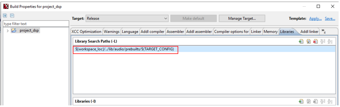
Realtek提供的库
libaudio_base.a 和 librpc_hal.a
路径: dsp/lib/audio/prebuilts/$(TARGET_CONFIG)。
libaudio_base.a:MCU 与 DSP 间的 RPC 框架,用于数据和信号同步
librpc_hal.a:硬件适配层,支持不同 RPC 平台
libxa_nnlib.a 和 libhifi5_dsp.a
libxa_nnlib.a:HiFi 5 神经网络库,路径为
dsp/lib/xa_nnlib/v1.7.0/bin/$(TARGET_CONFIG)/Releaselibhifi5_dsp.a:NatureDSP 信号处理库,路径为
dsp/lib/lib_hifi5/project/hifi5_library/bin/$(TARGET_CONFIG)/Release
DSP 布局
DSP 默认布局
We use a linker support package (LSP) to describe the layout of DSP. A LSP specifies object files to pull into an executable using a specific memory map, and is used as a convenient short-hand for telling the linker what it needs for a particular target environment. Refer to Xtensa Linker Support Packages (LSPs) Reference Manual (dspdoclsp_rm.pdf) for more information.
Here is the sketch of the default layout:

Here is the LSP seen from Xplorer:
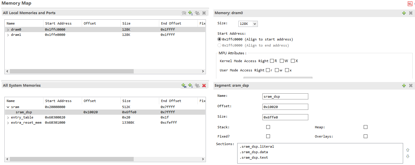
DSP can use sram_dsp, entry_table and extra_reset_mem for system memory, and DRAM 0/1 for local memory. Reset vector address will be placed in entry_table. DRAM 0/1 can only be used to store data.
For Call0 ABI, code AND data can be stored in sram_dsp and extra_reset_mem.
For Window ABI: code can only be stored in extra_reset_mem, data can be stored in sram_dsp and extra_reset_mem.
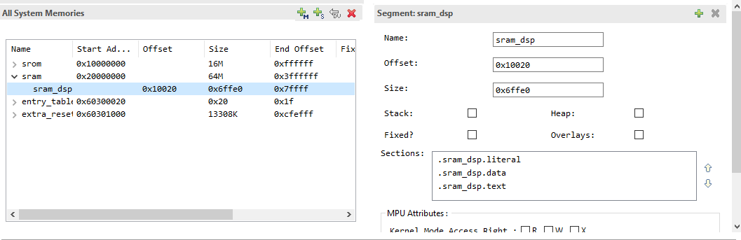
Placing Codes/Data into SRAM
There is a segment called sram_dsp in the default LSP: RTK_LSP. Putting codes or data into this area may have an effect on the performance of the whole project.
Using C Language Extensions
If the function to be placed into SRAM is:
void place_into_sram();
You should do this:
extern void place_into_sram()__attribute__ ((section(".sram_dsp.text")));
void place_into_sram(){
  //detailed implentation
   }
If you need to put an array into SRAM, you can do like this:
__attribute__ ((section(".sram_dsp.data"))) int array_in_psram[100];
Compiler Flags to Rename Sections
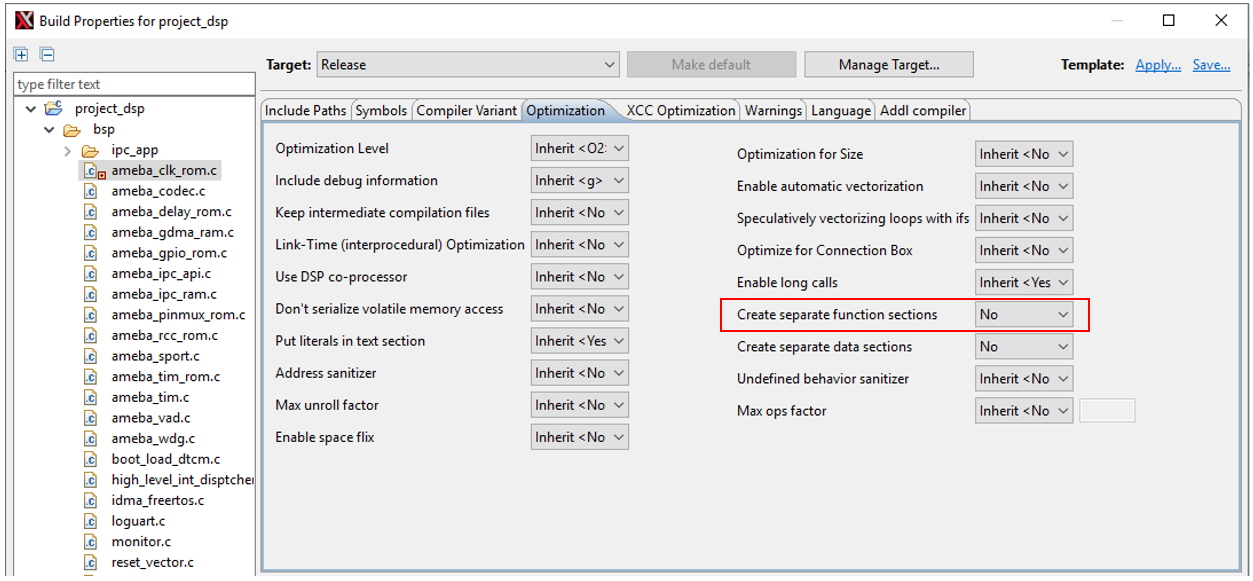
If all functions in
ameba_clk_rom.cneeds to be placed in SRAM, right click on this file, and chooseBuild Properties. And in the new window, set values to No for items in the box.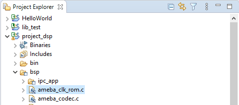
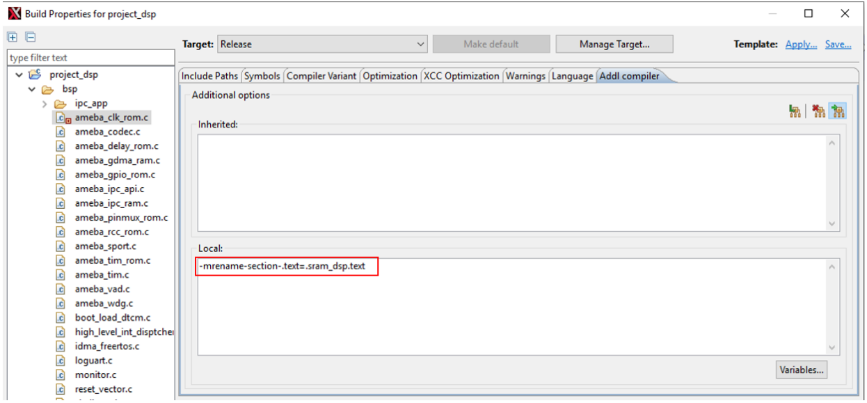
Switch to Addl compiler tab, add an option as follows:
Changing Default Layout of LSP
MCU and DSP share the PSRAM and SRAM, but DTCM is exclusive to DSP. When the layout of MCU changes, the LSP of DSP should change accordingly. For DSP memory layout, the memory addresses of DTCM and SRAM generally remain default, and only the start and end addresses of PSRAM need to be adjusted. We only need to use a python script to adjust the PSRAM space of the DSP, and then modify the MCU layout file accordingly according to the output of the script. The specific operation method is as follows:
Enter the directory:
{SDK}\project\img_utilitycd {SDK}/project/img_utility
With the command
python lsp_modify.py, you can get the current DSP PSRAM address from output:>> python lsp_modify.py Current LSP psram: Start Address: 0x60300000, End Address: 0x61000000, Size: 0xd00000 Invalid input. Please enter the start and end addresses in hex. Example: "python lsp_modify.py 0x60300000 0x61000000" DSP link script change FAIL.
With the command
python lsp_modify.py <start address in hex> <end address in hex>, you will get a new lsp:>> python lsp_modify.py 0x60400000 0x60A00000 Current LSP psram: Start Address: 0x60300000, End Address: 0x61000000, Size: 0xd00000 New LSP psram: Start Address: 0x60400000, End Address: 0x60a00000, Size: 0x600000 Warning : 'entry_table' start address not aligned to MPU min alignment (is 0x60400020, min alignment is 0x00001000) Warning : MPU region size smaller than min region size (0x60400020 - 0x60400040, is 32 must be at least 4096 bytes) Warning : 'unused' start address not aligned to MPU min alignment (is 0x60400040, min alignment is 0x00001000) New linker scripts generated in ../../project/RTK_LSP/RI-2021.8/HIFI5_PROD_1123_asic_UPG/RTK_LSP/ldscripts Change MCU layout (amebalite_layout.ld) PSRAM_DSP_START to 0x60400000
In the example, we adjust the PSRAM start/end positions to 0x60400000/0x60A00000. Since the MPU table automatically generated by the script, the address alignment warning above can be ignored without any adverse effects.
Add KEEP in the link script
RTK_LSPldscriptself32xtensa.x:.ipc_table : ALIGN(4) { _ipc_table_start = ABSOLUTE(.); KEEP(*(.ipc_table)) . = ALIGN (4); _ipc_table_end = ABSOLUTE(.); } >psram0_seg :psram0_phdr .command : ALIGN(4) { _command_start = ABSOLUTE(.); KEEP(*(.command)) . = ALIGN (4); _command_end = ABSOLUTE(.); } >psram0_seg :psram0_phdr
Change the layout file ({SDK}amebalite_gcc_projectamebalite_layout.ld ) according to the output of the script:
#define PSRAM_DSP_START (0x60400000)Recompile the DSP and MCU projects.
备注
Before using the script, make sure the bin directory of Xtensa tool has been added to the system or user path. Otherwise the executable file cannot be found. This script needs python3.
If you changed other MPU properties, please synchronize previous modifications on the newly generated
mpu_table.c. And compile the newmpu_table.cin the project.
其他注意事项
iDMA
The iDMA can transfer data from PSRAM or SRAM to DTCM. DTCM is a fast data memory in which data can be fetched within one clock cycle. Therefore, using the iDMA to move large blocks of data into DTCM for calculation can often improve performance. However, the use of iDMA has the following restrictions:
地址限制
The iDMA can only move data between system memory (SRAM and PSRAM) and local memory (DRAM 0/1), or within local memory. Only transfers between system memories are not allowed.
Although the DTCM (DRAM) space is a continuous 256KB, our DTCM is actually composed of two DRAM memories (each with a size of 128K). The iDMA cannot transfer across DRAM boundary (boundary address: 0x1ffe0000), so if the transfer crosses the middle border, then iDMA address error IDMA_ERR_WRITE_ADDR will be reported. You can bypass this limitation by doing two moves. There is also no performance penalty for performing the transfer twice.
中断注册和使能
If you need to use iDMA interrupts, not only need to register and enable interrupts, but also add control descriptor DESC_NOTIFY_W_INT when adding start iDMA transfer task. Otherwise, the interrupt will not enter the corresponding handler.
idma_register_interrupts(0, (os_handler)done_handler,  (os_handler)error_handler);
idma_copy_desc(dst_data, src_data, DATA_SIZE, DESC_NOTIFY_W_INT);
Refer to the iDMA example in our SDK and Xtensa docs sys_sw_rm.pdf.
FreeRTOS SyStick
The SyStick value obtained by calling xTaskGetTickCountFromISR in the interrupt handler is not accurate. This API interface is to obtain the SyStick value before the system enters WATI. The SyStick value will not be updated until the interrupt handler finishes executing. We do not recommend using the SyStick value directly.
缓存行
In the dsp_wrapper.h file, we wrap three D-Cache operation functions:
DCache_Clean
DCache_Invalidate
DCache_CleanInvalidate
When using DMA, be sure to pay attention to the operation of the cache:
In DCache_Invalidate operation, if length is not an integer multiple of the cacheline (128 Bytes), it will invalidate the entire cacheline. This will cause data stored in the same cacheline to be lost.
In DCache_Clean operation, if DMA has refreshed the memory, executing DCache_Clean again will overwrite the old data in the cache to the memory, resulting in invalid DMA fetch.
MPU Entry
If the user needs to make more detailed memory protection settings, he can add new MPU entries based on the default MPU table. The total available MPU entry number is 16. The default SDK configuration uses 7 entries. Note that the mpu_table.c files in the RTK_LSP path and project_dsp path should be modified simultaneously.
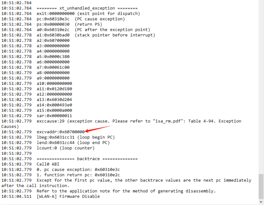
An example of the modification method is as follows: For example, we need to reserve a memory area in the memory address (0x60700000 - 0x60800000) in PSRAM that DSP cannot access it:
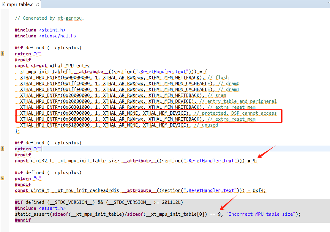
If the DSP accesses a protected address, the following crash log will be printed: