General Purpose Input/Output (GPIO)
Introduction
Architecture
GPIO driver follows Linux’s GPIO subsystem. GPIO lib provides GPIO interface to user space. The GPIO software architecture is illustrated in the following figure.

GPIO software architecture
For details of Linux GPIO system, refer to https://www.kernel.org/doc/html/v5.4/driver-api/gpio/index.html?highlight=gpio.
Implementation
GPIO driver is implemented as following files:
Driver location |
Introduction |
|---|---|
<linux>/drivers/rtkdrivers/gpio/Kconfig |
GPIO driver Kconfig |
<linux>/drivers/rtkdrivers/gpio/Makefile |
GPIO driver Makefile |
<linux>/drivers/rtkdrivers/gpio/realtek-gpio.c |
GPIO functions. |
<linux>/drivers/rtkdrivers/gpio/realtek-gpio.h |
GPIO related function declaration, macro definition, structure definition and the other header files quoted |
Configuration
DTS Configuration
GPIO DTS node:
gpioa: gpio@4200D000 {
   compatible = "realtek,ameba-gpio";
   gpio-controller;
   #gpio-cells = <2>;
   reg = <0x4200D000 0x400>;
   rtk,gpio-bank = <0>;
   interrupt-controller;
   #interrupt-cells = <2>;
   interrupts = <GIC_SPI 9 IRQ_TYPE_LEVEL_HIGH>;
   clocks = <&rcc RTK_CKE_GPIO>;
};
gpiob: gpio@4200D400 {
   compatible = "realtek,ameba-gpio";
   gpio-controller;
   #gpio-cells = <2>;
   reg = <0x4200D400 0x400>;
   rtk,gpio-bank = <1>;
   interrupt-controller;
   #interrupt-cells = <2>;
   interrupts = <GIC_SPI 10 IRQ_TYPE_LEVEL_HIGH>;
   clocks = <&rcc RTK_CKE_GPIO>;
};
gpioc: gpio@4200D800 {
   compatible = "realtek,ameba-gpio";
   gpio-controller;
   #gpio-cells = <2>;
   reg = <0x4200D800 0x400>;
   rtk,gpio-bank = <2>;
   interrupt-controller;
   #interrupt-cells = <2>;
   interrupts = <GIC_SPI 11 IRQ_TYPE_LEVEL_HIGH>;
   clocks = <&rcc RTK_CKE_GPIO>;
};
The DTS Configurations of GPIO are listed in the following table.
Property |
Description |
Default |
Configurable? |
|---|---|---|---|
compatible |
The description of GPIO driver. |
realtek,ameba-gpio |
No |
reg |
The hardware address and size for GPIO device.
|
No |
|
interrupts |
The GIC number of GPIO device.
|
No |
|
gpio-controller |
Indicates device node is a GPIO controller. |
No |
|
#gpio-cells |
Indicates how many cells are needed to specifically describe a GPIO. |
2 |
No |
interrupt-controller |
Indicates device node is an interrupt controller. |
No |
|
#interrupt-cells |
Indicates how many cells are needed to specifically describe a GPIO interrupt. |
2 |
No |
realtek,gpio-bank |
GPIO port index: 0: portA 1: portB 2: portC |
No |
|
clocks |
The clock of GPIO device. |
No |
Build Configuration
Select :
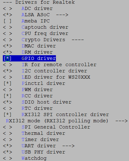
GPIO driver
APIs for User Space
sysfs
Platforms which use the gpiolib implementors framework may choose to configure a sysfs user interface to GPIOs.
Build Configuration
Select :
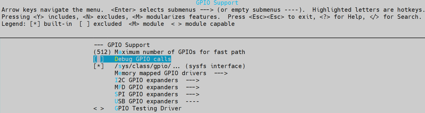
sysfs interface
sysfs Node
Node |
Introduction |
Value |
|---|---|---|
/sys/class/gpio/export |
Open GPIO |
GPIO pin number |
/sys/class/gpio/unexport |
Close GPIO |
GPIO pin number |
/sys/class/gpio/gpioX/direction |
GPIO direction |
in/out |
/sys/class/gpio/gpioX/value |
GPIO value |
0/1 |
/sys/class/gpio/gpioX/active_low |
GPIO low level is active |
0/1 |
/sys/class/gpio/gpioX/edge |
GPIO pin edge trigger type |
none/rising/falling/both |
备注
X is GPIO number.
The attribute files listed above under the gpioX path are all readable and writeable.
Usage
When operating a pin, the first step is to determine its number. This chip supports three independent GPIO IP: Port A (0~31), Port B (0~31), and Port C (0~7). BSP GPIO driver numbers all pins uniformly starting from 0 to 71. i.e. GPIOA-0 pin number is 0, and GPIOC-7 pin number is 71.
Alternatively, you can get the starting value of this group’s GPIO number through the base file in gpiochipX, and then the base plus the offset of the pin within the group is this GPIO pin number.
gpiochipX |
label (GPIOA/B/C) |
base |
ngpio |
|---|---|---|---|
gpiochip0 |
GPIO0 |
0 |
32 |
gpiochip32 |
GPIO1 |
32 |
32 |
gpiochip64 |
GPIO2 |
64 |
8 |
备注
Base: starting number of pin.
Ngpio: how many pins of this port.
X = base + offset, for example, GPIOB-8 pin number X = 32 + 8 = 40.
Shell
Command |
Introduction |
|---|---|
echo X > /sys/class/gpio/export |
Open GPIO |
echo X > /sys/class/gpio/unexport |
Close GPIO |
echo out > /sys/class/gpio/gpioX/direction |
Set GPIO direction as output |
echo in > /sys/class/gpio/gpioX/direction |
Set GPIO direction as input |
echo 1 > /sys/class/gpio/gpioX/value |
Set GPIO value to 1 |
echo 0 > /sys/class/gpio/gpioX/value |
Set GPIO value to 0 |
echo 1 > /sys/class/gpio/gpioX/active_low |
Set GPIO low level active |
echo 0 > /sys/class/gpio/gpioX/active_low |
Set GPIO high level active (default) |
echo none > /sys/class/gpio/gpioX/edge |
Set GPIO to non-interrupt pin |
echo rising > /sys/class/gpio/gpioX/edge |
Set GPIO pin as rising edge trigger |
echo falling > /sys/class/gpio/gpioX/edge |
Set GPIO pin as falling edge trigger |
echo both > /sys/class/gpio/gpioX/edge |
Set GPIO pin as both edge trigger |
cat /sys/class/gpio/gpioX/direction |
Get GPIO direction |
cat /sys/class/gpio/gpioX/value |
Get GPIO value |
cat /sys/class/gpio/gpioX/edge |
Get GPIO edge |
cat /sys/class/gpio/gpioX/active_low |
Get GPIO active low setting |
Output test
Export one GPIO pin to user space.
echo X > /sys/class/gpio/export
Set GPIO direction as output.
echo out > /sys/class/gpio/gpioX/direction
Set GPIO logic value to 1.
echo 1 > /sys/class/gpio/gpioX/value
Set GPIO logic value to 0.
echo 0 > /sys/class/gpio/gpioX/value
Unexport the GPIO pin.
echo X > /sys/class/gpio/unexport
Input test
Export one GPIO pin to user space.
echo X > /sys/class/gpio/export
Set GPIO direction as input.
echo in > /sys/class/gpio/gpioX/direction
Get GPIO logic value.
cat /sys/class/gpio/gpioX/value
Unexport the GPIO pin.
echo X > /sys/class/gpio/unexport
Application
Write the test code according to the method of reading and writing files above.
Output test
Export one GPIO pin to user space.
int export_fd = open("/sys/class/gpio/export", O_WRONLY);
write(export_fd, "X", sizeof("X"));
close(export_fd);
Set GPIO direction as output.
int direction_fd = open("/sys/class/gpio/gpioX/direction", O_WRONLY);
write(direction_fd, "out", sizeof("out"));
close(direction_fd);
Set GPIO logic value to 1.
int gpiovalue_fd = open("/sys/class/gpio/gpioX/value", O_WRONLY);
write(gpiovalue_fd, "1", sizeof("1"));
close(gpiovalue_fd);
Set GPIO logic value to 0.
int gpiovalue_fd = open("/sys/class/gpio/gpioX/value", O_WRONLY);
write(gpiovalue_fd, "0", sizeof("0"));
close(gpiovalue_fd);
Unexport the GPIO pin.
int unexport_fd = open("/sys/class/gpio/unexport", O_WRONLY);
write(unexport_fd, "X", sizeof("X"));
close(unexport_fd);
Input test
Export one GPIO pin to user space.
int export_fd = open("/sys/class/gpio/export", O_WRONLY);
write(export_fd, "X", sizeof("X"));
close(export_fd);
Set GPIO direction as input.
int direction_fd = open("/sys/class/gpio/gpioX/direction", O_WRONLY);
write(direction_fd, "in", sizeof("in"));
close(direction_fd);
Get GPIO logic value.
char value;
int gpiovalue_fd = open("/sys/class/gpio/gpioX/value", O_RDONLY);
read(gpiovalue_fd, &value, 1);
close(gpiovalue_fd);
Unexport the GPIO pin.
int unexport_fd = open("/sys/class/gpio/unexport", O_WRONLY);
write(unexport_fd, "X", sizeof("X"));
close(unexport_fd);
Interrupt test
Export one GPIO pin to user space.
int export_fd = open("/sys/class/gpio/export", O_WRONLY);
write(export_fd, "X", sizeof("X"));
close(export_fd);
Set GPIO direction as input.
int direction_fd = open("/sys/class/gpio/gpioX/direction", O_WRONLY);
write(direction_fd, "in", sizeof("in"));
close(direction_fd);
Set GPIO trigger type. Trigger type can be set to one of the following values:
rising,falling,both.int edge_fd = open("/sys/class/gpio/gpioX/edge", O_WRONLY); write(edge_fd, "rising", sizeof("rising")); close(edge_fd);
Poll GPIO value wait for interrupt happen, and read GPIO value when interrupt happens.
char val;
struct pollfd pfd;
pfd.events = POLLPRI;
pfd.fd = open("/sys/class/gpio/gpioX/value", O_RDONLY);
int ret = poll(&pfd, 1, -1);
if ((ret > 0) && (pfd.revents & POLLPRI)) {
   read(pfd.fd, &val, 1));
}
Unexport the GPIO pin.
int unexport_fd = open("/sys/class/gpio/unexport", O_WRONLY);
write(unexport_fd, "X", sizeof("X"));
close(unexport_fd);
Char Device
The GPIO can be used as a char device, and the GPIO controller char device is /dev/gpiochipX.
Ioctl operation could get gpiochip info and test specific GPIO pin.
备注
/dev/gpiochip0 GPIOA
/dev/gpiochip1 GPIOB
/dev/gpiochip2 GPIOC
IOCTL Command
IOCTL command defined in linux/gpio.h, so user main application must include linux/gpio.h.
IOCTL Command |
Description |
|---|---|
GPIO_GET_CHIPINFO_IOCTL |
Get gpiochip information, including name label and how many GPIO lines of this gpiochip. |
GPIO_GET_LINEINFO_IOCTL |
Get GPIO line information, including specific pin information. Such as name and flags. |
GPIO_GET_LINEHANDLE_IOCTL |
Get control of specific line, and then perform read and write operation on file descriptor. |
GPIO_GET_LINEEVENT_IOCTL |
Get event control of specific line, when an interrupt happens, read operation could get interrupt trigger timestamp. |
Usage
Get GPIO info test
Open GPIO char device.
int fd = open("/dev/gpiochp0", O_WRONLY);
Get GPIO chip information.
struct gpiochip_info info;
ioctl(fd, GPIO_GET_CHIPINFO_IOCTL, &info);//get GPIOA information
Get GPIO line information.
struct gpioline_info line_info;
line_info.line_offset = X;//get GPIOA pin X information
ioctl(fd, GPIO_GET_LINEINFO_IOCTL, &line_info);
Close GPIO char device.
close(fd);
Output test
Open GPIO char device.
int fd = open("/dev/gpiochp0", O_WRONLY);
Get specific GPIO line handle.
struct gpiohandle_request rq;
rq.lineoffsets[0] = offset;//offset in this gpio chip
rq.flags = GPIOHANDLE_REQUEST_OUTPUT;
rq.lines = 1;//one pin
ioctl(fd, GPIO_GET_LINEHANDLE_IOCTL, &rq);
close(fd);
Set GPIO pin value.
struct gpiohandle_data data;
data.values[0] = value;
ioctl(rq.fd, GPIOHANDLE_SET_LINE_VALUES_IOCTL, &data);
Close GPIO char device.
close(rq.fd);
Input test
Open GPIO char device.
int fd = open("/dev/gpiochp0", O_WRONLY);
Get specific GPIO line handle.
struct gpiohandle_request rq;
rq.lineoffsets[0] = offset;
rq.flags = GPIOHANDLE_REQUEST_OUTPUT;
rq.lines = 1;
ioctl(fd, GPIO_GET_LINEHANDLE_IOCTL, &rq);
close(fd);
Get GPIO pin value.
struct gpiohandle_data data;
ioctl(rq.fd, GPIOHANDLE_GET_LINE_VALUES_IOCTL, &data);
printf("Read value:%d\n",data.values[0]);
Close GPIO char device.
close(rq.fd);
Interrupt test
Open GPIO char device.
int fd = open("/dev/gpiochp0", O_WRONLY);
Get specific GPIO line event handle. Trigger type can be set to one of the following values: GPIOEVENT_EVENT_RISING_EDGE, GPIOEVENT_EVENT_FALLING_EDGE, (GPIOEVENT_EVENT_FALLING_EDGE|GPIOEVENT_EVENT_RISING_EDGE).
struct gpioevent_request event_req;
event_req.lineoffset = offset;
event_req.handleflags  = GPIOHANDLE_REQUEST_INPUT;//must set
event_req.eventflags = GPIOEVENT_EVENT_RISING_EDGE;
ioctl(fd, GPIO_GET_LINEEVENT_IOCTL, &event_req);
close(fd);
Poll GPIO value wait for an interrupt to happen, and get interrupt trigger timestamp.
struct gpioevent_data event_data;
struct pollfd pfd;
pfd.fd = event_req.fd;
pfd.events = POLLIN;
int ret = poll(&pfd, 1, -1);
if ((ret > 0)&&(pfd.revents & POLLIN)) {
   read(event_req.fd, &event_data, sizeof(event_data));
   printf("event_data.timestamp:%llu,.id:%d \n",event_data.timestamp, event_data.id);//id for edge trigger type, 1:rising edge,2:falling edge.
}
Close GPIO char device.
close(event_req.fd);
UIO
Each UIO device is accessed through a device file and several sysfs attribute files.
The device file will be called /dev/uio0 for the first device, and /dev/uio1, /dev/uio2 and so on for subsequent devices.
Interrupts are handled by reading from /dev/uioX. A blocking read() from /dev/uioX will return as soon as an interrupt occurs.
You can also use poll() on /dev/uioX to wait for an interrupt. The integer value read from /dev/uioX represents the total interrupt count.
You can use this number to figure out if you missed some interrupts.
Details of Linux UIO system, refer to https://www.kernel.org/doc/html/v5.4/driver-api/uio-howto.html.
Configuration
DTS Configuration
GPIO DTS UIO node:
gpio-uio-test {
   compatible = "generic-uio";
   status = "okay";
   interrupt-parent = <&gpioa>;
   interrupts = <15 IRQ_TYPE_EDGE_BOTH>;
};
Property |
Description |
Configurable |
|---|---|---|
compatible |
The description of UIO driver. Default: “generic-uio”. |
No |
interrupt-parent |
GPIOA group |
Yes |
interrupts |
This GPIO hardware interrupt number is 15, corresponding to the GPIOA pin 15. Trigger type: IRQ_TYPE_EDGE_BOTH |
Yes |
At the same time, add uio_pdrv_genirq.of_id=generic-uio to the bootargs property in the chosen node.
Build Configuration
Select :
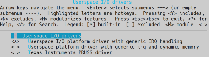
UIO driver
Usage
Interrupt test:
Open GPIO UIO device.
int uio_fd = open("/dev/uio0", O_RDWR);
Write 1 to unmask the interrupt, must be set every time.
uint32_t uio_int = 1;
write(uio_fd, &uio_int, sizeof(uio_int));
Poll GPIO UIO device and wait for the interrupt happen, could read interrupt count value.
struct pollfd pfd;
int uio_int;
pfd.events = POLLIN;
pfd.fd =uio_fd;
int ret = poll(&pfd, 1, -1);
if (ret > 0) {
   read(pfd.fd, &uio_int, 1));
}
Close GPIO UIO device.
close(uio_fd);
APIs for Kernel Space
Legacy APIs
API |
Description |
|---|---|
gpio_request |
Request a GPIO |
gpio_direction_output |
Set the GPIO direction to output |
gpio_direction_input |
Set the GPIO direction to input |
gpio_set_value |
Set the GPIO value (GPIO is in output direction) |
gpio_get_value |
Get the GPIO value |
gpio_free |
Free a GPIO |
gpio_export |
Export a GPIO through sysfs |
gpio_unexport |
Reverse effect of |
of_get_named_gpio_flags |
Get a GPIO number and flags for GPIO API |
gpiochip_add_data |
Register a gpiochip. |
gpiochip_remove |
Unregister a gpiochip. |
gpio_set_debounce |
Set GPIO debounce function |
gpio_to_irq |
Get GPIO pin virtual IRQ |
Refer to <linux>/Documentation/driver-api/gpio/legacy.rst for more details.
Descriptor-based APIs
API |
Description |
|---|---|
gpiod_get |
Obtain a GPIO for a given GPIO function |
gpiod_put |
Dispose of a GPIO descriptor. |
gpiod_direction_output |
Set the GPIO direction to output. |
gpiod_direction_input |
Set the GPIO direction to input. |
gpiod_set_value |
Assign a gpio’s value. (contexts that cannot sleep) |
gpiod_get_value |
Get the GPIO value. (contexts that cannot sleep) |
gpiod_set_debounce |
Set GPIO debounce function |
Refer to <linux>/Documentation/driver-api/gpio/consumer.rst for more details.
Usage
Output test
Get GPIO pin index.
gpio_index = of_get_named_gpio_flags(np, "test-gpios", 0, &flags);
Request a GPIO.
gpio_request(gpio_index, NULL);
Set GPIO direction to output. The initial value is 0.
gpio_direction_output(gpio_index, 0);
Write a logic value 1 to the specified pin of output port.
gpio_set_value(gpio_index, 1);
Get the logic value from specified pin of output port, and check the value.
gpio_get_value(gpio_index);
Free the GPIO pin.
gpio_free(gpio_index);
Input test
Get GPIO pin index.
gpio_index = of_get_named_gpio_flags(np, "test-gpios", 0, &flags);
Request a GPIO.
gpio_request(gpio_index, NULL);
Set GPIO direction to input.
gpio_direction_input(gpio_index);
External pull the GPIO pin high or low.
Get the logic value from specified pin of input port, and check the value.
gpio_get_value(gpio_index);
Free the GPIO pin.
gpio_free(gpio_index);
Interrupt test
Get GPIO pin index.
gpio_index = of_get_named_gpio_flags(np, "test-gpios", 0, &flags);
Initialize a completion variable.
reinit_completion(struct completion *x);
Request a GPIO.
gpio_request(gpio_index, NULL);
Get GPIO virq.
int virq = gpio_to_irq(gpio_index);
Request a trigger type. Trigger type can be set to one of the following values: IRQF_TRIGGER_RISING, IRQF_TRIGGER_FALLING, IRQF_TRIGGER_HIGH, IRQF_TRIGGER_LOW, (IRQF_TRIGGER_FALLING | IRQF_TRIGGER_RISING).
request_irq(virq, rtk_gpio_irq_handler, trigger_type, "gpio_irq", NULL);
GPIO can be configured to either include or exclude a debounce capability by setting
rtk,db_enable = "okay"and config debouce time.gpio_set_debounce(gpio_index,db_div_cnt);
备注
virq is the virtual IRQ number, you can use gpio_to_irq(gpio_index)() to get the specified pin’s virq.
External trigger, and wait for completion of the task.
wait_for_completion_timeout(struct completion *x, unsigned long timeout);
Free the IRQ.
free_irq(virq, NULL);
Free the GPIO pin.
gpio_free(gpio_index);
For more details, GPIO demo for kernel space is located at <test>/gpio. Refer to readme.txt in this directory.