Architecture
The SDIO host driver follows Linux MMC subsystem. The architecture is shown in following figure.

MMC architecture
The MMC framework is divided into 3 layers: MMC host driver, MMC core and MMC card driver. The MMC card driver registers the MMC subsystem as a block device, and the upper layer can access MMC subsystem through the block device with file system.
The MMC core implements the core logic of bus and MMC/SD/SDIO protocols. MMC host driver is implemented to connect host controller with MMC core, and SDIO driver is implemented on this layer.
Implementation
The SDIO host driver is implemented as following files:
Driver location |
Introduction |
|---|---|
<linux>/drivers/rtkdrivers/mmc/Kconfig |
SDIO host driver Kconfig |
<linux>/drivers/rtkdrivers/mmc/Makefile |
SDIO host driver Makefile |
<linux>/drivers/rtkdrivers/mmc/rtk-mmc.c |
SDIO host driver. |
<linux>/drivers/rtkdrivers/mmc/rtk-mmc.h |
SDIO host driver head file. |
Configuration
DTS Configuration
The DTS node is defined in <dts>/rtl8730e-ocp.dtsi.
sdioh: sdioh@400D0000 {
   compatible = "realtek,ameba-sdiohost";
   reg = <0x400D0000 0x8000>;
   interrupts = <GIC_SPI 38 IRQ_TYPE_LEVEL_HIGH>;
   clocks = <&rcc RTK_CKE_SDH>;
   status = "okay";
};
The following table is property description:
Property |
Description |
Configurable? |
|---|---|---|
compatible |
ID to match the driver and device |
No |
reg |
Register resource |
No |
interrupts |
SPI interrupt |
No |
clocks |
SDIO clock node |
No |
status |
SDIOH inyrttupt status |
No |
DTS nodes of pinctrl are defined in <dts>/rtl8730e-pinctrl.dtsi.
sdioh_pins: sdioh@0 {
   pins {
      pinmux = <REALTEK_PINMUX('B', 27, SDIO)>, // SD_CMD
               <REALTEK_PINMUX('B', 28, SDIO)>, // SD_CLK
               <REALTEK_PINMUX('C', 0, SDIO)>, // SD_CD
               <REALTEK_PINMUX('B', 29, SDIO)>, // SD_D0
               <REALTEK_PINMUX('B', 25, SDIO)>, // SD_D1
               <REALTEK_PINMUX('B', 26, SDIO)>, // SD_D2
               <REALTEK_PINMUX('B', 30, SDIO)>; // SD_D3
               bias-pull-up;
               slew-rate = <0>;
               drive-strength = <0>;
   };
};
The following table is pinmux description:
Property |
Description |
Configurable? |
|---|---|---|
pinmux |
Pin definition of SDIO host |
Yes |
bias-pull-up |
Pin pull status |
Yes |
slew-rate |
Pin voltage slew rate |
No |
drive-strength |
Pin drive strength |
No |
备注
Configure the pin according to the actual condition. If using 1-bit mode, SD_D1, SD_D2, SD_D3 can be annotated. If card detect and card protect function are not used, SD_CD, SD_WP can be annotated.
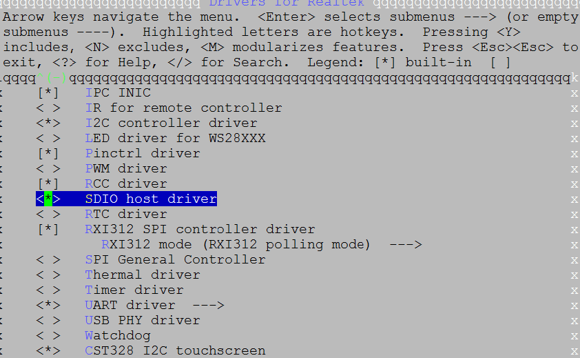
Build Configuration
Select :
APIs
APIs for User Space
The MMC subsystem provides user space interfaces:
dev/mmcblk0dev/mmcblk0p1
User should mount the interface to a directory so that SDIO device can be accessed directly through the directory.
备注
Interfaces could be changed according to the actual conditions.
Take SD card as example. Once SD card plug into cable, MMC subsystem will response soon and create 2 device node – /dev/mmcblk0 and /dev/mmcblk0p1. User should mount it to file system if system does not do this automatically.
Mount SD card to file system:
mount /dev/mmcblk0pN /mnt/sdcard
Locate to SD card directory:
cd /mnt/sdcard
Create a directory in SD card:
mkdir test_dirCreate a file in SD card directory test_dir:
touch test.txtWrite contents to the file
test.txtecho helloworld > test.txt
Read the file
test.txtcat test.txt
Refer to demo code to get more details. SDIO host demo is located at <test>/sdioh.
APIs for Kernel Space
None.