概述
架构
The IR driver of Realtek follows Linux framework: RC core, IR core and LIRC system. The LIRC provides IR interfaces to user space. The IR software architecture is illustrated below.

IR software architecture
For more details of Linux remote control system, refer to https://www.kernel.org/doc/html/v5.4/media/kapi/rc-core.html?highlight=remote%20controller.
IR is included in Linux Remote Control part.
实现
IR driver is implemented as following files:
Driver location |
Introduction |
|---|---|
<linux>/drivers/rtkdrivers/ir/Kconfig |
IR driver Kconfig |
<linux>/drivers/rtkdrivers/ir/Makefile |
IR driver Makefile |
<linux>/drivers/rtkdrivers/ir/ir-realtek.c |
IR functions |
<linux>/drivers/rtkdrivers/ir/ir-realtek.h |
IR related function declaration, macro definition, structure definition and the other header files quoted. |
配置
DTS 配置
IR DTS excerpts are as follows:
ir: ir@0x400EE000 {
   compatible = "realtek,ameba-ir";
   reg = <0x400EE000 0x30>;
   interrupts = <GIC_SPI 49 IRQ_TYPE_LEVEL_HIGH>;
   clocks = <&rcc RTK_CKE_IRDA>;
   rtk,ir-receiver = <0>;
   rtk,ir-tx-encode = <1>;
   rtk,ir-rx-auto = <1>;
   rtk,ir-cnt-thred-type = <1>;
   rtk,ir-cnt-threshold = <30000>;
   rtk,ir-rx-trigger-mode = <0>;
   rtk,ir-idle-level = <0>;
   rtk,ir_rx_inverse = <0>;
   status = "disabled";
};
The DTS Configurations of IR are listed in the following table.
Property |
Description |
Configurable? |
|---|---|---|
compatible |
The description of IR driver: |
No |
reg |
The hardware address and size for IR device: <0x400EE000 0x30>. |
No |
interrupts |
The GIC number of IR device: <GIC_SPI 49 IRQ_TYPE_LEVEL_HIGH>. |
No |
clocks |
The clock of IR device: <&rcc RTK_CKE_IRDA>. |
No |
rtk,ir-receiver |
|
0/1 |
rtk,ir-tx-encode |
Setting 1 to transmit scancode. When setting 0, the encode and decode shall be done by user space, IR driver only transmit the raw
data provided by user space.
|
0/1 |
rtk,ir-rx-auto |
|
0/1 |
rtk,ir-cnt-threshold |
The time to judge termination. Setting 30000 here means that if hardware receives no data for 30ms,
represents the end of a transfer.
|
No |
rtk,ir-cnt-thred-type |
|
0/1 |
rtk,ir-rx-trigger-mode |
The edge Rx process start with:
|
0/1/2 |
rtk,ir-idle-level |
|
0/1 |
rtk,ir_rx_inverse |
|
0/1 |
status |
Whether enable this device.
|
Yes |
The pin assignments of IR are listed in the following table.
Pin name |
Pin function |
pinctrl description |
|---|---|---|
PB10 |
IR_RX |
<&ir_pins> |
PB11 |
IR_TX |
|
PA25 |
IR_TX |
Shall add manually. |
PB22 |
IR_RX |
|
PB25 |
IR_TX |
Shall add manually. |
PB26 |
IR_RX |
|
PA3 |
IR_TX |
Shall add manually. |
PA4 |
IR_RX |
|
PA17 |
IR_TX |
Shall add manually. |
The pinmux can be chosen according to the specific conditions. Refer to pinctrl Application note for more details.
编译配置
Select for remote controller:
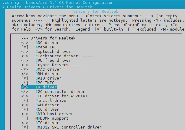
IR Driver
API
APIs for User Space
IR interfaces for user space are provided by https://www.kernel.org/doc/html/v5.4/media/uapi/rc/lirc-header.html.
Here are some commonly used API to control IR devices. Refer to https://www.kernel.org/doc/html/v5.4/media/uapi/rc/lirc-func.html for more details.
Interfaces |
Introduction |
|---|---|
ir_lirc_open |
Open an IR device |
ir_lirc_close |
Close an IR device |
ir_lirc_ioctl |
Configure IR parameters |
ir_lirc_transmit_ir |
Call IR driver to send a message |
ir_lirc_read |
Read the scancode received |
IR Sending Example
Open IR device
fd = open("/dev/lirc0", O_RDWR);
Change IR mode to scancode transmit
#include <linux/lirc.h>
int to_set = LIRC_MODE_SCANCODE;
ret = ioctl(fd, LIRC_SET_SEND_MODE, &to_set);
Configure IR scancode for sending
timestamp is not important.
keycode and flags shall be set to 0.
rc_proto shall be set to RC_PROTO_NEC.
scancode to be send shall be organized in NEC rule, otherwise, the transfer will return with an error.
#include <linux/lirc.h>
struct lirc_scancode {
   __u64  timestamp;
   __u16  flags;
   __u16  rc_proto;
   __u32  keycode;
   __u64  scancode;
};
struct lirc_scancode scan;
scan.rc_proto = RC_PROTO_NEC;
scan.scancode = 0xEA158A75;
scan.keycode = 0;
scan.timestamp = 0;
scan.flags = 0;
Send IR scancode: a return of
0means success; otherwise, it means failure.ret = write(fd, &scan, sizeof(scan));
IR Receiving Example
Open IR device
fd = open("/dev/lirc0", O_RDWR);
When IR driver is configured as receive-mode, open IR means to start IR receiving.
This procedure can be ignored, because IR device will be opened automatically at next procedure.
Open event handler
getevent -l &
The symbol
&is used to make event notification parallel to IR Rx process.Wait for IR signal. The opposite emitter should also be an infrared light emitting semiconductor.
When received, the waveform will be decoded by NEC protocol, and then becomes scancode. scancode will be submitted to event handler and inform user space as an event.
Refer to
<test>/irfor more details.
APIs for Kernel Space
None.