Introduction
General timer could work in three Linux subsystems.
Clock source – general timer can be clock source of time subsystem.
MFD timer – just to implement basic timing function of general timer in MFD subsystem.
PWM – timer8 is PWM timer and it is implemented in PWM subsystem.
The three sections will be described separately.
Clock Source
Introduction
Architecture
The generic timer can be used as clock source or clock event. Typical usage is as broadcast timer in time subsystem. Architecture of Linux time subsystem is shown below.
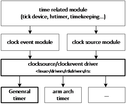
Time subsystem software architecture
Time related modules (tick devices, hrtimer, timekeeping, etc.) depend on clock source module and clock event module, which depend on hardware timer. General timers are hardware timer so it can be used as clock source module and clock event module.
General timers’ frequency is not enough to make it a tick device for system. Actually, CPU local timer is the tick device to generate tick for system.
However, general timer still plays a role in time subsystem, that is, as a broadcast timer. The existence of broadcast timer is useful for the time subsystem, which make the CPU local timer can use oneshot mode. Also, the system can stop the CPU local timer in idle state to save power.
All Generic timers can be used as clock source.
备注
Timer0 could be used as system timer for LP and NP system, so it is not recommended to use Timer0 as clock source.
Implementation
Clock source driver for general timer is implemented as following files:
Driver location |
Introduction |
|---|---|
<linux>/drivers/rtkdrivers/clocksource/Kconfig |
Clock source driver Kconfig |
<linux>/drivers/rtkdrivers/clocksource/Makefile |
Clock source driver Makefile |
<linux>/drivers/rtkdrivers/clocksource/timer-rtk.c |
Clock source driver for general timer. |
Configuration
DTS Configuration
DTS configuration is as follows. Take TIMER1 as an example:
timer1: timer@4200B200 {
   compatible = "realtek,ameba-timer-clk";
   reg = <0x4200B200 0x200>;
   interrupts = <GIC_SPI 1 IRQ_TYPE_LEVEL_HIGH>;
   clocks = <&rcc RTK_CKE_TIM1>;
};
The description of DTS properties is as below:
Property |
Description |
Configurable? |
|---|---|---|
compatible |
ID to match the driver and device |
No |
reg |
Register resource. |
No |
interrupts |
SPI interrupt |
No |
clocks |
General timer clock node |
No |
Build Configuration
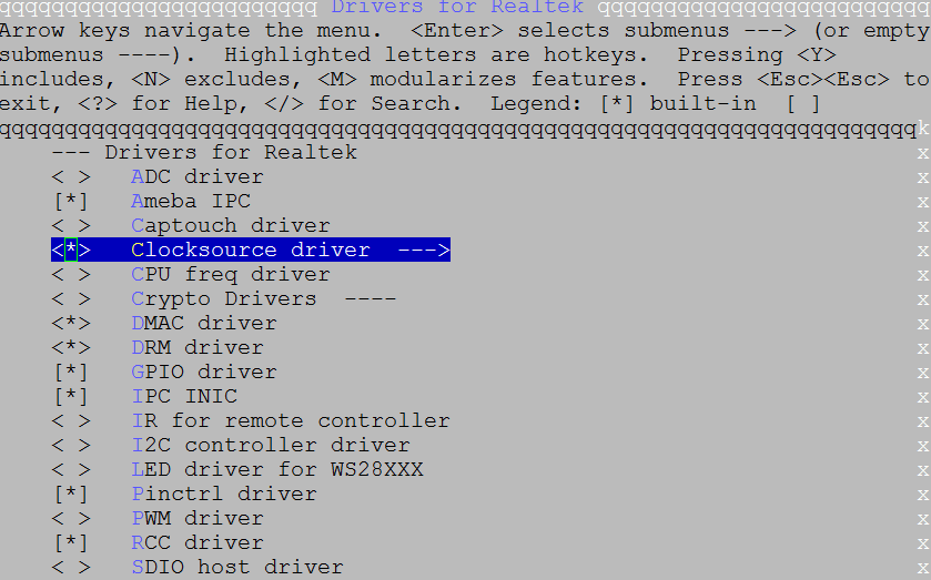
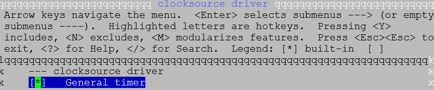
Select Device Drivers > Drivers for Realtek > Clocksource driver > General timer:
APIs
APIs for User Space
None.
APIs for Kernel Space
Refer to timers_information to get more information.
MFD Timer
Introduction
Software Architecture
General timers’ basic timing functions are put in MFD (Multi-function Device) subsystem. Due to the emergence of a kind of peripheral devices with multiple functions, Linux provides a MFD subsystem.
Actually, MFD timer driver does not use any contents of MFD subsystem, So MFD architecture is not shown here.
MFD timer driver just provide APIs for kernel so that kernel can use timer interrupt function simply.
All generic timers can be MFD Timer.
备注
Timer0 is system timer for LP and NP, so it is not recommended to use Timer0 as MFD timer.
Implementation
MFD timer driver is implemented as following files:
Driver location |
Introduction |
|---|---|
<linux>/drivers/rtkdrivers/mfd_timer/Kconfig |
MFD timer driver Kconfig |
<linux>/drivers/rtkdrivers/mfd_timer/Makefile |
MFD timer driver Makefile |
<linux>/drivers/rtkdrivers/mfd_timer/rtk-timer.c |
MFD timer driver for general timer. |
Configuration
DTS configuration
DTS configuration is as follows. Take timer2 as an example:
timer2: timer@4200B400 {
   compatible = "realtek,ameba-timer";
   reg = <0x4200B400 0x200>;
   interrupts = <GIC_SPI 2 IRQ_TYPE_LEVEL_HIGH>;
   clocks = <&rcc RTK_CKE_TIM2>;
};
The following is property description:
Property |
Description |
Configurable? |
|---|---|---|
compatible |
ID to match the driver and device |
No |
reg |
Register resource. |
No |
interrupts |
SPI interrupt |
No |
clocks |
General clock node |
No |
Build Configuration
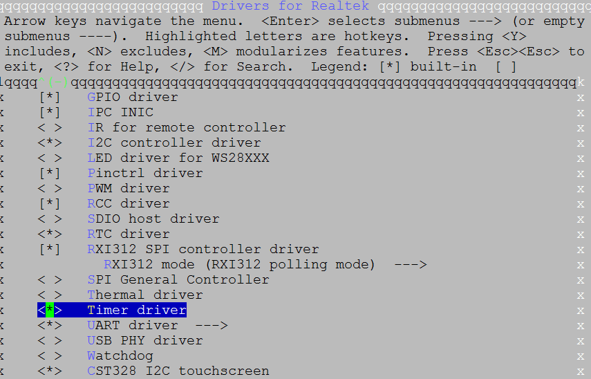
Select Device Drivers > Drivers for Realtek > Timer driver:
APIs
APIs for User Space
None.
APIs for Kernel Space
API |
Description |
|---|---|
rtk_gtimer_init |
Initilize a mfd-timer with a specific channel number. |
rtk_gtimer_dynamic_init |
Initilize a mfd-timer with any free channel. |
rtk_gtimer_deinit |
Deinitilize timer. |
rtk_gtimer_int_config |
Enable or disable timer update interrupt. |
rtk_gtimer_int_clear |
Clear interrupt flag. |
rtk_gtimer_change_period |
Change timer period. |
rtk_gtimer_start |
Start or stop timer(counter will not reset to 0). |
The following is an example to show how to use kernel APIs.
Init MFD timer device.
rtk_gtimer_init(Tim_Idx, 10000000, timer_callback, cbdata);
Configure MFD timer interrupt.
rtk_gtimer_int_config(Tim_Idx, 1);
Start the timer.
rtk_gtimer_start(Tim_Idx, 1);
Timer interrupt will rise after 10000000ns and then executes handler time_callback which use parameter cbcata.
PWM
Introduction
Architecture
The PWM timer can be used as PMW device. The architecture of Linux PWM subsystem is shown below.

PWM subsystem architecture
Application controls PWM device through sysfs layer, while kernel controls it through API. PWM core implements core logic of PWM subsystem.
备注
Only timer 8 can be PWM device.
Implementation
PWM driver is implemented as following files:
Driver location |
Introduction |
|---|---|
<linux>/drivers/rtkdrivers/pwm/Kconfig |
PWM timer driver Kconfig |
<linux>/drivers/rtkdrivers/pwm/Makefile |
PWM timer driver Makefile |
<linux>/drivers/rtkdrivers/pwm/rtk-pwm.c |
PWM driver for PWM timer. |
Configuration
DTS configuration
As PMW timer also can be general timer, PWM node is in timer node. DTS configuration is as follows.
timer8: timer@4100A000 {
   compatible = "realtek,ameba-timer";
   #address-cells = <1>;
   #size-cells = <1>;
   reg = <0x4100A000 0x200>;
   interrupts = <GIC_SPI 57 IRQ_TYPE_LEVEL_HIGH>;
   clocks = <&rcc RTK_CKE_TIM_PWM>;
   pwm: pwm@0 {
      compatible = "realtek,ameba-pwm";
      status = "disabled";
   };
};
The following table is property description:
Property |
Description |
Configurable? |
|---|---|---|
compatible |
ID to match the driver and device |
No |
reg |
Register resource. |
No |
status |
Whether enable this device.
|
Yes |
DTS nodes of pinctrl are defined in <dts>/rtl8730e-pinctrl.dtsi.
pwm_pins: pwm@0 {
   pins1 {
      pinmux = <REALTEK_PINMUX('B', 14, PWM)>, // HS_PWM0
               <REALTEK_PINMUX('B', 15, PWM)>,     // HS_PWM1
               <REALTEK_PINMUX('B', 16, PWM)>,     // HS_PWM2
               <REALTEK_PINMUX('A', 11, PWM)>,     // HS_PWM3
               <REALTEK_PINMUX('A', 12, PWM)>;     // HS_PWM4
      bias-pull-up;
      slew-rate = <0>;
      drive-strength = <0>;
   };
   pins2 {
      pinmux = <REALTEK_PINMUX('A', 13, PWM)>;  // HS_PWM5
      bias-pull-up;
      swd-disable;
      slew-rate = <0>;
      drive-strength = <0>;
   };
};
The following table is property description:
Property |
Description |
Configurable? |
|---|---|---|
pinmux |
Pin definition of PWM |
Yes |
bias-pull-up |
Pin pull status |
Yes |
slew-rate |
Pin voltage slew rate |
No |
drive-strength |
Pin drive strength |
Yes |
备注
Refer to pinmux specification to choose pin assignment.
Build Configuration
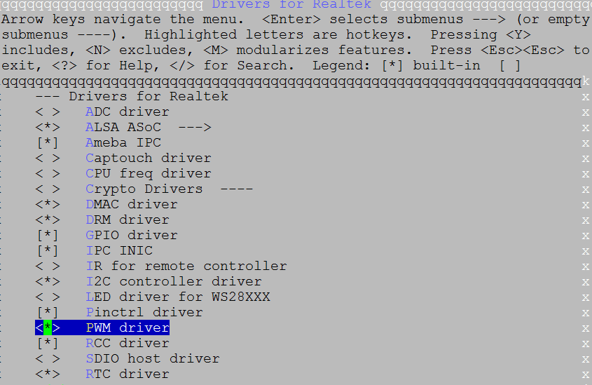
Select Device Drivers > Drivers for Realtek > PWM driver:
APIs
APIs for User Space
PWM subsystem provides user space interface: /sys/class/pwm
User can control PWM device through sysfs layer. The PWM node is /sys/class/pwm/pwmchip0.
The following is an example:
User should choose a channel to export firstly. Command to export channel 2:
echo 2 > /sys/class/pwm/pwmchip0/export
Command to configure period to 2000000ns:
echo 2000000 > /sys/class/pwm/pwmchip0/pwm2/period
Command to configure duty cycle to 25%:
echo 500000 > /sys/class/pwm/pwmchip0/pwm2/duty_cycle
Command to enable PWM channel:
echo 1 > /sys/class/pwm/pwmchip0/pwm2/enable
Then, channel 2 will output square wave with 500Hz frequency and 25% duty cycle.
PWM demo for user space is located at <test>/pwm. Refer to PWM demo to get more information.
APIs for Kernel Space
PWM subsystem provides APIs for Kernel Space.
API |
Description |
|---|---|
pwm_request |
Request a PWM device |
pwm_free |
Free a PWM device |
pwm_apply_state |
Atomically apply a new state to a PWM device |
pwm_adjust_config |
Adjust the current PWM config to the PWM arguments |
pwm_config |
Change a PWM device configuration |
pwm_enable |
Start a PWM output toggling |
pwm_disable |
Stop a PWM output toggling |
Refer to PWM_information to get more details.
The following is an example to show how to use kernel APIs.
Request PWM device.
pwm_dev= pwm_request(pwm_channel_id, NULL);
Configure and apply PWM setting
ret = pwm_config(pwm_dev, 500000, 1000000);
Enable PWM output.
ret = pwm_enable(pwm_dev);