Pin Controller (Pinctrl)
Introduction
Architecture
The pinctrl driver follows Linux’s pin control subsystem. Pin control subsystem deals with:
Enumerating and naming controllable pins
Multiplexing of pins, pads, fingers, etc.
Configuration of pins, pads, fingers, etc., such as software-controlled biasing specific pins, such as pull-up/down, open drain, load capacitance.
The pinctrl software architecture is shown below.
pinctrl software architecture
Refer to https://www.kernel.org/doc/html/v5.4/driver-api/pinctl.html?highlight=pinctrl for more details of Linux pinctrl system.
Implementation
The pinctrl driver is implemented as following files:
Driver location |
Introduction |
|---|---|
<linux>/drivers/rtkdrivers/pinctrl/Kconfig |
Pinctrl driver Kconfig |
<linux>/drivers/rtkdrivers/pinctrl/Makefile |
Pinctrl driver Makefile |
<linux>/drivers/rtkdrivers/pinctrl/realtek-pinctrl-ameba.c |
Pinctrl functions table and initialization |
<linux>/drivers/rtkdrivers/pinctrl/realtek-pinctrl.c |
Pinctrl functions |
<linux>/drivers/rtkdrivers/pinctrl/realtek-pinctrl.h |
Pinctrl related function declaration, macro definition, structure definition and the other header files quoted |
<linux>/include/dt-bindings/realtek/pinctrl/realtek-ameba-pinfunc.h |
Pinctrl definition |
Configuration
DTS Configuration
The DTS for pinctrl is defined in <dts>/rtl8730e-pinctrl.dtsi.
pinctrl Driver DTS Configuration
The parent part of pinctrl is listed in the following table.
Property |
Description |
Default |
Configurable? |
|---|---|---|---|
compatible |
The description of IR driver. |
realtek,ameba-pinctrl |
No |
reg |
The hardware address and size for IR device. |
<0x42008A00 0x120> |
No |
address-cells |
Indicates sub node address length, unit is 32 bits. |
1 |
No |
size-cells |
Indicates sub node length, unit is 32 bits. |
1 |
No |
The pinctrl is a platform bus-device-driver model. In Linux kernel, when one platform device and platform driver matches, before its driver/bus probe, Linux kernel will automatically execute device and pinctrl subsystem binding, and auto configure the corresponding pin function and features.
pinctrl Configuration for Other Drivers
The way to support other drivers is to define a child-node under the pinctrl node. The format is:
[driver_name]_pins_[pin_name]: [abbreviation]@[pin_num] {
  pins {
    pinmux = <REALTEK_PINMUX('[A/B/C]', [pin_num], [hardware_driver_id])>,
      <REALTEK_PINMUX('[A/B/C]', [pin_num], [hardware_driver_id])>,
      <REALTEK_PINMUX('[A/B/C]', [pin_num], [hardware_driver_id])>,
      <REALTEK_PINMUX('[A/B/C]', [pin_num], [hardware_driver_id])>;
    bias-pull-up;
    slew-rate = <0>;
    drive-strength = <0>;
  };
};
If user need to add more pins (2 pins for example here), the format is:
[driver_name]_pins_[pin_name]: [abbreviation]@[pin_num] {
  pins1 {
    pinmux = <REALTEK_PINMUX('[A/B/C]', [pin_num], [hardware_driver_id])>,
    <REALTEK_PINMUX('[A/B/C]', [pin_num], [hardware_driver_id])>,
    <REALTEK_PINMUX('[A/B/C]', [pin_num], [hardware_driver_id])>,
    <REALTEK_PINMUX('[A/B/C]', [pin_num], [hardware_driver_id])>;
    bias-pull-up;
    slew-rate = <0>;
    drive-strength = <0>;
  };
  pins2 {
    pinmux = <REALTEK_PINMUX('[A/B/C]', [pin_num], [hardware_driver_id])>;
    bias-pull-up;
    swd-disable;
    slew-rate = <0>;
    drive-strength = <0>;
  };
};
Descriptions in ‘[]’ should be specified by driver.
[driver_name]_pins_[pin_name] will be used when a driver is adding pinctrl to its own dts node.
[A/B/C] means PA, PB or PC group, refer to pinmux hardware for more information.
The [pin_num] of PA1 is 1, refer to pinmux hardware for more information.
[hardware_driver_id] can be found in
<sdk>/sources/kernel/<linux>/include/dt-bindings/realtek/pinctrl/realtek-ameba-pinfunc.h. Each [hardware_driver_id] inrealtek-ameba-pinfunc.hmeans a mapping to its hardware function. Example: when adding I2C pinmux, just use I2C macro here.
Other description of properties is listed in the following table.
Property |
Description |
Configurable? |
|---|---|---|
pinmux |
Defines pin bank, number, and function. |
Yes |
pull type |
Pull type, it can be set as one of the following:
|
Yes |
slew rate |
PAD slew rate control, it can be set to 0 or 1. |
0/1 |
drive-strength |
PAD driving ability control, it can be set to 0 or 1. |
No |
swd-disable |
Disable pad SWD function. |
Optional |
audio-share-enable |
Disable pad audio function. |
Optional |
Note
Pins means a group of pin functions and properties. If a device has multiple properties, the sub-nodes can be named pins1, pins2 … rather than pins.
If PA13 or PA14 is not used to set SWD function, it needs to add property swd-disable.
If PA18 ~ PB6 are not set to Audio function, it needs to add property audio-share-enable.
pinctrl Quote
The pinmux for drivers is board specific. When configuring pinmux for a specified driver. The steps are as follows:
Find the board specified DTS in directory: <dts> by the board name. Example: for 256M nand common board, the DTS is
rtl8730elh-va8-xxx.dts.Find the entire name of this driver [driver_name], such as i2c0.
Add the pinctrl quote:
&[driver_name]{
  pinctrl-names = "default";
  pinctrl-0 = <&[driver_name]_pins_[pin_name]>;
};
[driver_name]_pins_[pin_name]: refer to pinctrl Configuration for Other Drivers
There will be several groups of pinmux with different [pin_name] but the same [driver_name]. Choose the currect one according to the board layout. Refer to hardware user guide for more details.
If the specific pinmux is not listed in pinctrl dts, find the corresponding [driver_name], and revise the [A/B/C], [pin_num] according to the guidance in pinctrl Configuration for Other Drivers
When there are multiple pinctrl state and phandle list, the node need to configure as following:
&[driver_name]{
pinctrl-names = "default", "sleep";
pinctrl-0 = [driver_name]_pins_[pin_name]>;
pinctrl-1 = [driver_name]_pins_[pin_name];
};
Build Configuration
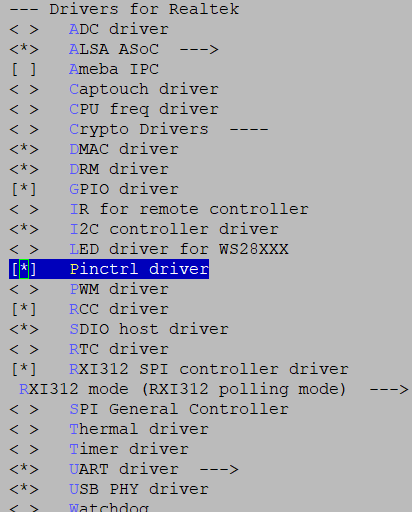
Select :

pinctrl driver
APIs
APIs for User Space
None.
APIs for Kernel Space
Items |
Description |
|---|---|
pinctrl_get |
Retrieves the pinctrl handle for a device |
pinctrl_put |
Decrease use count on a previously claimed pinctrl handle |
devm_pinctrl_get |
Resource managed |
devm_pinctrl_put |
Resource managed |
pinctrl_loopup_state |
Retrieves a state handle from a pinctrl handle |
pinctrl_select_state |
Select/activate/program a pinctrl state to HW |
pinctrl_get_select_default |
Retrieves the pinctrl handle for a device, and set the pinctrl handle to default state. |
pinctrl_get_select |
Retrieves the pinctrl handle for a device, and set the pinctrl handle to select state. |
devm_pinctrl_get_select_default |
Resource managed |
devm_pinctrl_get_select |
Resource managed |
devm_pinctrl_register |
Resource managed version of |
pinctrl_register |
Register a pin controller device |
pinctrl_unregister |
Unregister pinmux |
To use pinmux, you can do as follows:
Request all pinctrl resource.
devm_pinctrl_get_select_default(dev)
Get pinctrl handle.
pinctrl = pinctrl_get(dev);
Retrieves a state handle from a pinctrl handle, such as “default” state.
pinctrl_lookup_state(pinctrl, "default");
Select a pinctrl state to HW.
pinctrl_select_state(pinctrl, state);
Release the pinctrl handle.
pinctrl_put(pinctrl);
Refer to https://www.kernel.org/doc/html/v5.4/driver-api/pinctl.html for more details.