Introduction
Architecture
Realtek’s audio driver follows Linux’s ALSA System on Chip (ASoC) architecture. ASoC provides better ALSA support for embedded system on chip processors and portable audio codecs.
ALSA - Advanced Linux Sound Architecture.
ASoC - ALSA System on Chip.
ASoC basically splits an embedded audio system into three re-usable component drivers:
Codec driver - The codec driver is platform-independent and contains audio controls, audio interface capabilities, codec DAPM definition and codec IO functions.
Platform driver - The platform driver contains audio DMA engine and audio interface drivers for that platform.
Machine driver - The machine driver handles any machine specific controls and audio events, e.g. turning on an AMP at the start of playback.
Realtek’s audio driver implements all above components, the architecture is illustrated in the following figure.

Implementation
The implementation of Realtek’s audio driver lies in the following directories.
Driver location |
Introduction |
|---|---|
<linux>/sound/soc/realtek/machine.c |
Machine driver. Describes which codec, dma, cpu_dai, codec_dai driver we use. |
<linux>/sound/soc/realtek/dma.c |
DMA driver. |
<linux>/sound/soc/realtek/sport.c |
cpu_dai driver, which is the SPORT driver of audio codec. |
<linux>/sound/soc/realtek/ameba_sport.c |
SPORT control APIs implementations. |
<linux>/sound/soc/realtek/ameba_audio_clock.c |
PLL clock framework. |
<linux>/sound/soc/realtek/ameba_audio_clock_driver.c |
PLL clock driver. |
<linux>/sound/soc/codecs/ameba-codec.c |
codec_dai driver and codec driver. |
<linux>/sound/soc/codecs/ameba_audio.c |
Codec control APIs implementations. |
Where <linux> means the kernel linux directory in sdk, which is <sdk>/kernel/linux-5.4 for kernel 5.4.x, and <sdk>/kernel/linux-6.6 for kernel 6.6.x, the same applies below.
Audio driver Kconfig:
<linux>/sound/soc/Kconfigsource "sound/soc/realtek/Kconfig"
Audio driver Makefile:
<linux>/sound/soc/Makefileobj-$(CONFIG_SND_SOC) += realtek/
Audio driver devices
The audio driver exports standard ALSA device to user space via
/dev/sndwhen it is built into system. Check the following device node list in/dev/sndat runtime to check if the audio driver is working correctly.
Device nodes |
Introduction |
|---|---|
controlC0 |
Control device node for audio. It’s used to set volume, mute, output device switch and input microphone number choice. |
pcmC0D0p |
Device node for SPORT0 and internal audio codec output. |
pcmC0D1c |
Device node for SPORT1 and internal audio codec input. |
pcmC0D2p |
Device node for SPORT2 I2S output. |
pcmC0D2c |
Device node for SPORT2 I2S input. |
pcmC0D3p |
Device node for SPORT3 I2S output. |
pcmC0D3c |
Device node for SPORT3 I2S input. |
The implementation supports the following audio types:
Audio Playback: Currently supports the following audio types for playback using pcmC0D0p/pcmC0D2p & pcmC0D3p.
Device node
Audio types
Format support
pcmC0D0p
Audio Format
SNDRV_PCM_FORMAT_S16_LE
SNDRV_PCM_FORMAT_S24_LE
pcmC0D0p
Channel
Mono
Stereo
pcmC0D0p
Sample Rate
8000
11025
16000
22050
32000
44100
48000
88200
96000
pcmC0D2p & pcmC0D3p
Audio Format
SNDRV_PCM_FORMAT_S16_LE
SNDRV_PCM_FORMAT_S20_LE
SNDRV_PCM_FORMAT_S24_LE
SNDRV_PCM_FORMAT_S32_LE
pcmC0D2p & pcmC0D3p
Channel
Mono
Stereo
Quad multi-io
Quad TDM
6 channel TDM
6 channel multi-io
8 channel TDM
8 channel multi-io
pcmC0D2p & pcmC0D3p
Sample Rate
8000
11025
16000
22050
32000
44100
48000
88200
96000
Audio Capture: Currently supports the following audio types for capture using pcmC0D1c/pcmC0D2c & pcmC0D3c.
Device node
Audio types
Format support
pcmC0D1c
Audio Format
SNDRV_PCM_FORMAT_S16_LE
SNDRV_PCM_FORMAT_S24_LE
pcmC0D1c
Channel
mono
Stereo
4 Channel (2 Channel Mic Data + 2 Channel Reference Data)
pcmC0D1c
Sample Rate
8000
11025
16000
22050
32000
44100
48000
88200
96000
pcmC0D2c & pcmC0D3c
Audio Format
SNDRV_PCM_FORMAT_S16_LE
SNDRV_PCM_FORMAT_S20_LE
SNDRV_PCM_FORMAT_S24_LE
SNDRV_PCM_FORMAT_S32_LE
pcmC0D2c & pcmC0D3c
Channel
Mono
Stereo
Quad multi-io
Quad TDM
6 channel TDM
6 channel multi-io
8 channel TDM
8 channel multi-io
pcmC0D2c & pcmC0D3c
Sample Rate
8000
11025
16000
22050
32000
44100
48000
88200
96000
Audio Control: Currently supports the following audio control settings using controlC0.
CTL No.
Type
Number
Name
Default Value
Introduction
0
INT
2
DAC Volume
128, 128
Left Channel/Right Channel Volume[0~175]
1
BOOL
2
DAC Mute
Off, Off
Left Channel/Right Channel mute
Off: unmute
On: mute
2
INT
1
AD0 Volume
47
ADC0 Volume[0~175]
3
INT
1
AD1 Volume
47
ADC1 Volume[0~175]
4
INT
1
AD2 Volume
47
ADC2 Volume[0~175]
5
INT
1
AD3 Volume
47
ADC3 Volume[0~175]
6
INT
1
AD4 Volume
47
ADC4 Volume[0~175]
7
INT
1
AD5 Volume
47
ADC5 Volume[0~175]
8
INT
1
AD6 Volume
47
ADC6 Volume[0~175]
9
INT
1
AD7 Volume
47
ADC7 Volume[0~175]
10
BYTE
5
MICBST AMIC1-5 GAIN
06, 06, 06, 06, 06
GAIN of 5 AMICS
GAIN can be (0, 1, 2, 3, 4, 5, 6, 7, 8)
11
INT
2
Zero Dect Timeout
0, 0
Left Channel/Right Channel zero detect timeout
0: 1024*16 samples
1: 1024*32 samples
2: 1024*64 samples
3: 64 samples
12
INT
1
Choice Device
0
0: Speaker output
1: Headphone output
13
INT
1
Choice MIC 0:AMIC 1:DMIC
0
0: Record from AMIC
1: Record from DMIC
14
BYTE
8
Choice AMIC tdm-8 slot
01, 02, 03, 03, 03, 03, 03, 03
Define the AMIC number used to capture data
15
BYTE
8
Choice DMIC tdm-8 slot
01, 02, 03, 04, 04, 04, 04, 04
Define the DMIC number used to capture data
Configuration
DTS Configuration
Audio DTS makes audio driver more flexible for different hardware. User can change DTS according to the specific hardware. Be aware that, after changing DTS, make sure it has no conflict with other modules.
In this section, <dts_dir> means the directory of dts files, which is <sdk>/kernel/linux-5.4/arch/arm/boot/dts for kernel 5.4.x, and <sdk>/kernel/linux-6.6/arch/arm/boot/dts/realtek/ameba for kernel 6.6.x.
Amplifier Configuration
Change the following DTS GPIO configuration of amplifier enable pins according to different boards.
Change
<dts_dir>/rtl8730e-pinctrl.dtsi.audio_ext_amp_pins:audio_ext_pin@0 { pins { pinmux = <REALTEK_PINMUX('B', 7, GPIO)>; //using PB7 for amplifier enable pin …… }; };Change your product’s amplifier pinmux setting in DTS. For example, if you launch generic_rtl8730elh_va8-eng, please change
<dts_dir>/rtl8730elh-va8-generic.dts.&codec{ pinctrl-names = "default"; pinctrl-0 = <&audio_ext_amp_pins>; ext_amp_gpio = <&gpiob 7 0>; };
SPORT Muti-io Configuration
The SPORT2/SPORT3 I2S is for data transmission with external audio codec. It can be TDM or multi-io. Configure it according to the hardware of your board.
Take the rtl8730elh-va8 demo board, generic project’s dts config for example.
Example: how to set SPORT2 as multi-io.
Change
<dts_dir>/rtl8730elh-va8-generic.dts.&sport2 { rtk,sport-multi-io = <1>; };
Example: how to set SPORT3 as TDM.
Change
<dts_dir>/rtl8730elh-va8-generic.dts.&sport3 { rtk,sport-multi-io = <0>; };
SPORT MCLK Output Multiplier Set
The SPORT2/SPORT3 I2S is for data transmission with external audio codec. Some external audio codec needs SPORT to provide MCLK to them. They may have requirements like:
External audio codec MCLK = multiplier * sport_MCLK
At this case, add the multiplier in DTS to notify SPORT driver the information, so that SPORT driver will calculate the right PLL clock for specific data streaming sample rate.
Take the rtl8730elh-va8 demo board, generic project’s dts config for example:
Change <dts_dir>/rtl8730elh-va8-generic.dts.
&sport2 {
   rtk,sport-mclk-multiplier = <256>
};
SPORT MCLK Maximum Value Set
The SPORT2/SPORT3 I2S is for data transmission with external audio codec. Some external audio codec needs SPORT to provide MCLK to them. They may have requirements like:
External audio codec MCLK <= fixed_sport_MCLK
At this case, add the maximum value of MCLK in DTS to notify SPORT driver the information, so that SPORT driver will calculate the right PLL clock for specific data streaming sample rate.
Take the rtl8730elh-va8 demo board, generic project’s dts config for example:
Change <dts_dir>/rtl8730elh-va8-generic.dts.
&sport2 {
   rtk,sport-mclk-fixed-max = <12288000>;
};
To be noticed: rtk,sport-mclk-multiplier and rtk,sport-mclk-fixed-max should not be set at the same time, otherwise driver will be confused.
SPORT Mode Set
The SPORT supports both master mode and slave mode.
Set the correct mode you need in your project’s dts. For example, if you launch generic_rtl8730elh_va8-eng, please change <dts_dir>/rtl8730elh-va8-generic.dts:
&sport2 {
   rtk,sport-mode = <0>; // 0,soc is master. 1, soc is slave.
};
SPORT Pinmux Set
The SPORT2/SPORT3 I2S needs to set the pinmux to interact with external codec.
The I2S pinmux is set in
<dts_dir>/rtl8730e-pinctrl.dtsi. If your board’s pinmux is different, config it. For example:i2s2_pins: i2s2@0 { pins { pinmux = <REALTEK_PINMUX('B', 14, I2S2)>,//change your pinmux <REALTEK_PINMUX('B', 15, I2S2)>, //change your pinmux <REALTEK_PINMUX('B', 16, I2S2)>, //change your pinmux <REALTEK_PINMUX('B', 17, I2S2)>, //change your pinmux <REALTEK_PINMUX('B', 18, I2S2)>, //change your pinmux <REALTEK_PINMUX('B', 19, I2S2)>, //change your pinmux <REALTEK_PINMUX('B', 20, I2S2)>; //change your pinmux bias-disable; //bias-disable/bias-pull-up/bias-pull-down slew-rate = <0>; drive-strength = <0>; }; }; i2s3_pins: i2s3@0 { pins { pinmux = <REALTEK_PINMUX('B', 7, I2S3)>, //change your pinmux <REALTEK_PINMUX('B', 8, I2S3)>, //change your pinmux <REALTEK_PINMUX('B', 9, I2S3)>, //change your pinmux <REALTEK_PINMUX('B', 29, I2S3)>, //change your pinmux <REALTEK_PINMUX('B', 30, I2S3)>, //change your pinmux <REALTEK_PINMUX('B', 31, I2S3)>, //change your pinmux <REALTEK_PINMUX('C', 0, I2S3)>; //change your pinmux bias-disable; //bias-disable/bias-pull-up/bias-pull-down slew-rate = <0>; drive-strength = <0>; }; };
Make sure to use the i2s pinmux in your project’s dts. For example, if you launch generic_rtl8730elh_va8-eng and need to use i2s2_pins in SPORT2, add i2s in the SPORT2 part in <dts_dir>/rtl8730elh-va8-generic.dts.
&sport2 {
   pinctrl-names = "default";
   spinctrl-0 = <&i2s2_pins>;
};
DMIC Configuration
DMIC is not enabled by default. If you want to test the DMIC, follow the steps below:
There are two groups of DMIC pinmux in <dts_dir>/rtl8730e-pinctrl.dtsi. Choose the one you use, and you can also change it according to your hardware.
dmic_pins_a: dmic@0 { // Fixed for EV730EL0_3V0 demo board
   pins {
      pinmux = <REALTEK_PINMUX('B', 21, DMIC)>,//change your pinmux
      <REALTEK_PINMUX('B', 22, DMIC)>;  //change your pinmux
      bias-disable;  //bias-disable/bias-pull-up/bias-pull-down
      slew-rate = <0>;
      drive-strength = <0>;
   };
};
dmic_pins_b: dmic@1 {
   pins {
      pinmux = <REALTEK_PINMUX('B', 16, DMIC)>, //change your pinmux
      <REALTEK_PINMUX('B', 17, DMIC)>,  //change your pinmux
      <REALTEK_PINMUX('B', 18, DMIC)>,  //change your pinmux
      <REALTEK_PINMUX('B', 19, DMIC)>,  //change your pinmux
      <REALTEK_PINMUX('B', 20, DMIC)>;  //change your pinmux
      bias-disable;  //bias-disable/bias-pull-up/bias-pull-down
      slew-rate = <0>;
      drive-strength = <0>;
   };
};
Make sure to use the dmic pinmux in your project’s dts. For example, if you launch generic_rtl8730elh_va8-eng and need to use dmic_pins_a, change <dts_dir>/rtl8730elh-va8-generic.dts.
&codec{
   pinctrl-names = "default", "default";
   pinctrl-0 = <&audio_ext_amp_pins>;
      pinctrl-1 = <&dmic_pins_a>;
      ext_amp_gpio = <&gpiob 7 0>;
};
Build Configuration
The configuration of audio driver is already set y by default.
To change audio driver configuration, type command, then select the menu in order.
make kernel_menuconfig

APIs
API for User Space
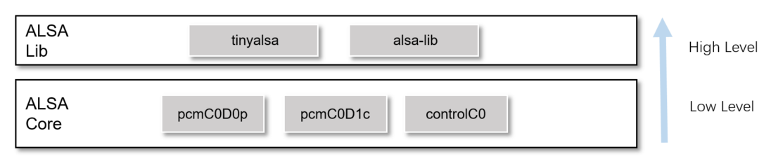
The audio driver exports two layers of interfaces to meet customer’s requirements.
API layers |
Introduction |
|---|---|
tinyalsa or ALSA-lib API |
Third-party user space API of Advanced Linux Sound Architecture |
ALSA open,close,ioctl API |
Standard Linux driver API |
The two layers of interfaces relationship is shown as below.
ALSA Core APIs
The audio driver exports standard ALSA interfaces to user space.
Interfaces |
Introduction |
|---|---|
open |
Open an ALSA device (pcmC0D0p, pcmC0D1c, pcmC0D2p, pcmC0D2c, pcmC0D3p, pcmC0D3c, controlC0) |
close |
Close an ALSA device |
ioctl |
Interaction with ALSA driver to read, write stream, or set volume/mute |
tinyalsa APIs
tinyalsa is a small library to interface with ALSA in the Linux kernel. It is open-source.
The aims are:
Provide a basic PCM and mixer API.
Avoid supporting complex and unnecessary operations, which could be dealt with at a higher level.
Control APIs
Here are some commonly used APIs to set control elements values.
Interfaces |
Introduction |
|---|---|
mixer_open |
Open a mixer |
mixer_close |
Close a mixer |
mixer_get_num_ctls |
Get number of mixer controls |
mixer_get_ctl |
Get mixer control of specific id |
mixer_ctl_get_name |
Get name of a mixer control |
mixer_get_ctl_by_name |
Get mixer control by name |
mixer_ctl_get_value |
Get value of mixer control |
mixer_ctl_set_value |
Set value of mixer control |
mixer_ctl_set_array |
Set array value of mixer control |
For more details of API, refer to github tinyalsa.
Here is an example showing how to use control APIs to set audio volume.
Create string of volume control:
char mixer_ctl_name[128] = "DAC Volume";
Call mixer_open to open
/dev/snd/controlC0:struct mixer * mixer = mixer_open(0); if (!mixer) { ALOGE("%s: Unable to open the mixer card"); }Get control by name:
struct mixer_ctl * ctl = mixer_get_ctl_by_name(mixer, mixer_ctl_name);
if (!ctl) {
   ALOGE("%s: Could not get ctl for %s", __func__, mixer_ctl_name);
   return -EINVAL;
}
Set volume value of control:
int volume[2];
volume[0] = MAX_VOLUME;//175
volume[1] = MAX_VOLUME;//175
mixer_ctl_set_array(ctl, volume, sizeof(volume) / sizeof(volume[0]));
If no need to use mixer, close it:
mixer_close(mixer);
mixer = NULL;
PCM APIs
Here are some commonly used PCM-related APIs.
Interfaces |
Introduction |
|---|---|
pcm_open |
Open a PCM |
pcm_close |
Close a PCM |
pcm_write |
Write PCM raw data to driver |
pcm_read |
Get PCM raw data from driver |
For more details of APIs, refer to github tinyalsa.
Here is an example showing how to use PCM APIs to render audio stream.
Create config of output stream:
struct pcm_config pcm_output_config = {
   .channels = 2,
   .rate = DEFAULT_OUT_SAMPLING_RATE,
   .period_size = SHORT_PERIOD_SIZE,
   .period_count = SHORT_PERIOD_COUNT,
   .format = PCM_FORMAT_S16_LE,
   .start_threshold = 0,
   .avail_min = 0,
};
Open the device node of playback /dev/snd/pcmC0D0p, with the config created in step 1.
struct pcm *out_pcm pcm_open(0, 0, PCM_OUT | PCM_MONOTONIC, &pcm_output_config);
Write audio raw data to ALSA driver:
if (out_pcm) {
   ret = pcm_write(out_pcm, (void *)buffer, bytes);
}else {
   ALOGE("out pcm is NULL!!!");
}
When write done, close PCM device node:
if(out_pcm) {
   pcm_close(out_pcm);
   out_pcm = NULL;
}
ALSA-lib APIs
ALSA-lib is a standard library to interface with ALSA in the Linux kernel. It is open-source.
The aims are:
The library offers 100% of the functionality of the kernel API.
The library adds major improvements in usability, making the application code simpler and better looking.
Future fixes or compatibility code may be placed in the library code instead of the kernel driver.
Control APIs
Here are some commonly used control APIs.
Interfaces |
Introduction |
|---|---|
snd_ctl_open |
Open sound control card |
snd_ctl_close |
Close sound control card |
snd_ctl_elem_info_get_id |
Get CTL element identifier of a CTL element id/info |
snd_ctl_elem_info_set_id |
Set CTL element identifier of a CTL element id/info |
snd_ctl_elem_info |
Get CTL element information |
snd_ctl_elem_read |
Get CTL element value |
snd_ctl_elem_write |
Set CTL element value |
For more details of APIs, refer to Alsa project control interface.
The example of control implementation can refer to the codes in alsa-utils: fwk/third_party/alsa-lib/alsa-utils-1.2.5.1/alsactl
PCM APIs
Here are some commonly used PCM APIs.
Interfaces |
Introduction |
|---|---|
snd_pcm_open |
Opens a PCM |
snd_pcm_close |
Close a PCM |
snd_pcm_info |
Obtain general (static) information for PCM handle |
snd_pcm_hw_params |
Install one PCM hardware configuration |
snd_pcm_prepare |
Prepare PCM for use |
snd_pcm_readi |
Read interleaved frames from a PCM |
snd_pcm_writei |
Write interleaved frames to a PCM |
For more details of APIs, refer to Alsa project pcm interface.
The example of PCM implementation can refer to the codes in alsa-utils: fwk/third_party/alsa-lib/alsa-utils-1.2.5.1/aplay
Audio-clock APIs
For internal audio codec, SPORT0 is for playback, SPORT1 is for capture. The audio input clock is XTAL 40M.
For external audio codec, SPORT2 / SPORT3 is for playback and capture. The audio input clock can be either XTAL 40M or audio PLL. If you set Sport MCLK output multiplier set as DTS Configuration, and the value is not 0, audio driver will automatically choose suitable audio PLL clock.
The aims of audio-clock APIs are:
Offer APIs for user to get the current clock for SPORT0 to SPORT3.
Offer APIs for user to achieve fine-tuning of audio PLL.
To use the audio-clock APIs, copy the header to your include path: <linux>/include/uapi/sound/rtk_audio_pll.h
Audio-clock APIs are calling through standard device node interfaces.
Interfaces |
Introduction |
|---|---|
open |
Open an audio PLL clock device: /dev/audio_pll_clk. |
close |
Close an audio PLL clock device. |
ioctl |
Interaction with audio clock driver to get clock information or achieve fine-tuning. |
rtk_audio_pll.h describes two important structures:
- struct micro_adjust_params is used to achieve fine-tuning.
struct audio_clock_infois used to get current clock forSPORT0toSPORT3.struct micro_adjust_params { /*can be PLL_24P576M, PLL_45P158M, or PLL_98P304M*/ unsigned int clock; /*can be #define PLL_AUTO, PLL_FASTER, or PLL_SLOWER*/ unsigned int action; /*can be any value between 0-1000*/ unsigned int ppm; }; struct audio_clock_info { /*user sets sport_index, to tell kernel which sport's clock info it needs*/ unsigned int sport_index; /*user gets clock info from kernel for the sport_index he sets*/ unsigned int clock; };
Here’s an example to get the clock info for SPORT2.
Open the audio PLL device node, and get the fd.
#define AUDIO_PLL_DEV "/dev/audio_pll_clk"
int fd = open(AUDIO_PLL_DEV, O_RDWR);
Do ioctl with cmd AUDIO_PLL_GET_CLOCK_FOR_SPORT to get the clock info.
Note that the info.sport_index should be set by application, so that driver will know which SPORT’s clock to get. However, the sport_index is a concept of hardware, you may wonder which SPORT is using. Check the PCM device node, for example, if audio is playing through audio device node pcmC0D2p, then it’s using SPORT2, so set
info.sport_index = 2.The relationship may be got from Implementarion Audio driver devices.
struct audio_clock_info info;
info.sport_index = 2;
ioctl(fd, AUDIO_PLL_GET_CLOCK_FOR_SPORT, &info);
If the device node is no longer used, close it.
close(fd);
Here’s an example to achieve fine-tuning of 98.304M PLL clock.
Open the audio PLL device node, and get the fd.
fd = open(AUDIO_PLL_DEV, O_RDWR);
   if(fd == -1) {
      printf("open %s fail \n", AUDIO_PLL_DEV);
}
Do ioctl with cmd AUDIO_PLL_MICRO_ADJUST to do fine-tuning.
In this case, you should put the clock to adjust in
params.clock, put the action(PLL_FASTER, PLL_AUTO, PLL_SLOWER) inparams.action, and put the ppm inparams.ppm.Take 98.304M for example:
PLL_AUTO: reset to auto 98.304M
PLL_FASTER: PLL clock faster than 98.304M
PLL_SLOWER: PLL clock slower than 98.304M
The actions will not cause superposition. For example, set PLL_FASTER 800ppm once and set PLL_FASTER 800ppm twice, the result is the same. The
params.ppmmeans the clock drift, the expected clock diff equals \(98.304M * ppm/1000000\).struct micro_adjust_params params; params.clock = PLL_98P304M; params.action = PLL_FASTER; params.ppm = 800; ioctl(fd, AUDIO_PLL_MICRO_ADJUST, ¶ms);
If the device node is no longer used, close it.
close(fd);
The test demo lies in tests/audio_pll.
Debug Tools
tinyalsa
tinyalsa is an open-source tool for testing tinyalsa-lib.
tinymix
tinymix is a tool to set mixer controls.
tinymix [options] [control name/#] [value to set]
The options are as follows:
Options |
Introduction |
|---|---|
-D,–card |
Use the given card # instead of 0. |
-a,–all-values |
Show all possible values/ranges for control. |
-t, –tabs-only |
Separate all output columns/values with tabs. |
-v, –value-only |
Show only the value for the selected control |
If you want to choose output device, set as follows:
tinymix "Choice Device 0: Spk 1: HEAPHONE" 0
If you want to set output volume, set as follows:
tinymix "DAC Volume" 100 100
If you want to set zero-dection timeout value, set as follows:
tinymix " Zero Dect TimeOut" 1 1
If you want to change MIC numbers for 2 channel-microphone data +2 channel-reference data, set as follows:
tinymix "Choice tdm-4 slot" 01 02 03 03
//chose amic1(mic-left),amic2(mic-right),amic3(ref-left),amic3(ref-right)
If you want to mute system, set as follows:
tinymix "DAC Mute" On
tinyplay
tinyplay is a tool to play PCM raw data.
tinyplay file.wav [options]
The options are as follows:
Options |
Introduction |
|---|---|
-D, –card |
Use the given card # instead of 0. |
-d,–device |
Use the given device # instead of 0. |
-p, –period-size|- |
Use the given period_size. |
-n, –period-count| |
Use the given period_count. |
If you want to play a wave, set as follows:
tinyplay ./file.wav -D 0 -d 0 -p 1024 -n 4
tinycap
tinycap is a tool to capture PCM raw data.
tinycap file.wav [options]
The options are as follows:
Options |
Introduction |
|---|---|
-D, –card |
Use the given card # instead of 0. |
-d,–device |
Use the given device # instead of 0. |
-c, –channels |
Use the given channel count. |
-r, –rate |
Use the given sample rate. |
-b, –bits |
Use the given format bits. |
-p, –period-size |
Use the given period_size. |
-n, –period-count |
Use the given period_count. |
-T, –capture-time |
Time for capturing data. |
If you want to capture a wave, set as follows:
tinycap ./file.wav -D 0 -d 1 -r 48000 -T 10
tinyhostless
tinyhostless is a tool to capture and send capture raw data to playback immediately.
tinyhostless [options]
The options are as follows:
Options |
Introduction |
|---|---|
-D,–card |
Use the given card. |
-P,–playback-device |
Use the given device for playback. |
-C,–capture-device |
Use the given device for capture. |
-p,–period-size |
Use the given period_size. |
-n,–period-count |
Use the given period_count. |
-c,–channel count |
Use the given channel_count. |
-r,–sample-rate |
Use the given sample rate. |
-l,–should-loop |
Should loop or not. |
-T,–playback-capture-time |
Playback-capture time. |
If you want to capture and send capture raw data to playback immediately, set as follows:
tinyhostless -D 0 -P 0 -C 1 -p 1024 -n 4 -c 2 -r 16000 -l -T 10
tinyalsa-extension
Realtek demo tool is used to test playback and capture, and mainly used in capturing 4 channel microphone data + reference data.
tinydownchplay
This test tool is only used in this case: User uses tinycap or record to capture a 4 channel raw data, which consists of 2 channel-microphone data, or 2 channel-reference data. Then user wants to separately play 2 channel-microphone data, or 2 channel-reference data.
The using of it is:
tinydownchplay file.wav [options]
The options are as follows:
Options |
Introduction |
|---|---|
-D, –card |
Use the given card # instead of 0. |
-d,–device |
Use the given device # instead of 0. |
-p, –period-size|- |
Use the given period_size. |
-n, –period-count| |
Use the given period_count. |
-c, –target-play-channel-count |
Target playing channel count. |
-s, –target-play-source |
Choose 0 for the first 2 channel raw data in 4channel original data to play. Choose 1 for the last 2 channel raw data in 4 channel original data to play. |
If you want to play 2 channel microphone raw data, set as follows:
tinydownchplay ./file.wav -D 0 -d 0 -p 1024 -n 4 -c 2 -s 0
If you want to play 2 channel reference raw data, set as follows:
tinydownchplay ./file.wav -D 0 -d 0 -p 1024 -n 4 -c 2 -s 1
tinylooptest
This test tool is only used in 88pin-test board in this case: User wants to quickly check that whether the 4 channel raw data capturing is fine.
The using of it is:
tinylooptest [options]
If you hear the reference data from left speaker, and hear the AMIC data from the right speaker, it means the test is successful.
The options are as follows:
Options |
Introduction |
|---|---|
-D,–card |
Use the given card. |
-P,–playback-device |
Use the given device for playback. |
-C,–capture-device |
Use the given device for capture. |
-p,–period-size |
Use the given period_size. |
-n,–period-count |
Use the given period_count. |
-c,–channel count |
Use the given channel_count. |
-r,–sample-rate |
Use the given sample rate. |
-l,–should-loop |
Should loop or not. |
-T,–playback-capture-time |
Playback-capture time. |
If you want test 4 channel data capturing, set as follows:
tinylooptest -D 0 -P 0 -C 1 -p 1024 -n 4 -c 4 -r 16000 -l -T 10
ALSA-util
Standard ALSA tools are for debugging ALSA-lib.
amixer
amixer is a tool to set mixer controls.
amixer <options> [command]
The options are as follows:
Options |
Introduction |
|---|---|
-c,–card |
Select the car. |
-D,–device |
Select the device. |
cget cID |
Get control contents for one control. |
cset cID P |
Set control contents for one control. |
controls |
Show all controls for given card. |
contents |
Show contents of all controls for given card. |
Here’s the example of setting volume:
amixer cset numid=1,iface=MIXER,name='DAC Volume' 175 175
To test the ALSA plugins, take DAC Volume for example:
amixer -D your_ctl_name cset numid=1,iface=MIXER,name='DAC Volume' 175 175
Note
Before this step, please add your file asound.conf into /etc directory on board.
aplay
aplay is a tool to play audio raw data.
aplay [OPTION]... [FILE]...
The options are as follows:
Options |
Introduction |
|---|---|
-D, –device |
Select PCM by name. |
-t, –file-type |
Set the file type, for example: wav, raw…. |
-f, –format |
Set the format of file. |
-c,–channel count |
Get control contents for one control. |
-r,–sample rate |
Set the sample rate of file. |
–period-size |
Get period size. |
–buffer-size |
Get ALSA buffer size. |
Here’s the example of playing audio wave through pcmC0D2p:
aplay -D hw:0,2 --period-size=1024 --buffer-size=4096 -t wav ./file.wav
To test the ALSA plugins:
aplay -Dplug:your_plug_name --period-size=1024 --buffer-size=4096 -t wav ./file.wav
Note
Before this step, please add your file asound.conf into /etc directory on board.
arecord
arecord is a tool to capture microphone data.
arecord [OPTION]... [FILE]...
The options are as follows:
Options |
Introduction |
|---|---|
-D, –device |
Select PCM by name. |
-t, –file-type |
Set the file type, for example: wav, raw…. |
-f, –format |
Set the format of file. |
-c,–channel count |
Get control contents for one control. |
-r,–sample rate |
Set the sample rate of file. |
-d,–duration |
Set the time of recording. |
–period-size |
Set period size. |
–buffer-size |
Set ALSA buffer size. |
Here’s the example of capturing audio wave data through pcmC0D1c:
arecord -D hw:0,1 -d 10 -r 48000 -f S16_LE -c 2 --period-size=1024 --buffer-size=4096 -t wav ./test.wav
To test the ALSA plugins:
arecord -Dplug:your_plug_name -d 5 -r 48000 -f S16_LE -c 2 --period-size=1024 --b
uffer-size=4096 -t wav ./test.wav
Note
Before this step, please add your file asound.conf into /etc directory on board.