Introduction
Architecture
ADC driver follows Linux’s Industrial I/O (IIO) subsystem. IIO provides ADC interface to user space. The ADC software architecture is illustrated in the following figure.
ADC software architecture contains the following parts:
IIO drivers: ADC drivers.
ADC: ADC driver.
Comparator: comparator driver, it is only used when ADC in comparator-assist mode.
IIO timers triggers: It is only used when ADC or comparator in timer-trigger mode.
IIO frameworks: IIO subsystem core drivers.
IIO user (kernel): for kernel use.
Application: User space use.
libiio: Libiio is an open source library for accessing IIO devices. It encapsulates access to
/sys/bus/IIO/devices(configure IIO) and/dev/IIO/deviceX(read / write IIO), and provides easy to test IIO command-line tools (iio_info / iio_readdev) and iiod server. For libiio source code, refer to github libiio.Demo: A simple example to show how to use ADC.
For more details of IIO, refer to kernel industrial.
Implementation
ADC driver is implemented in the following files.
File |
Description |
|---|---|
<linux>/drivers/rtkdrivers/adc/Kconfig |
ADC driver Kconfig |
<linux>/drivers/rtkdrivers/adc/Makefile |
ADC driver Makefile |
<linux>/drivers/rtkdrivers/adc/realtek-adc.c |
ADC functions. |
<linux>/drivers/rtkdrivers/adc/realtek-adc.h |
ADC related function declaration, macro definition, structure definition and the other header files quoted |
<linux>/drivers/rtkdrivers/adc/realtek-comparator.c |
ADC comparator functions. It is used when ADC in comparator-assist mode. |
<linux>/drivers/rtkdrivers/adc/realtek-comparator.h |
Comparator related function declaration, macro definition, structure definition and the other header files quoted |
Configuration
DTS Configuration
ADC DTS node:
adc: adc@42012000 {
   compatible = "realtek,ameba-adc";
   #address-cells = <1>;
   #size-cells = <1>;
   #io-channel-cells = <1>;
   reg = <0x42012000 0x100>,
      <0x42012800 0x100>;
   interrupts = <GIC_SPI 14 IRQ_TYPE_LEVEL_HIGH>;
   clocks = <&rcc RTK_CKE_CTC>, <&rcc RTK_CKE_ADC>;
   clock-names = "rtk_ctc_clk", "rtk_adc_clk";
   rtk,adc-mode = <0>; // 0: Software-trigger mode, 1: Automatic mode, 2: Timer-trigger mode
   rtk,adc-timer-period = <200000000>; // Useful only in timer-trigger mode. Unit: ns. Range: 100ms~2s
   //rtk,adc-channels = <0>, <1>, <2>, <6>;
   //rtk,adc-diff-channels = <4 5>;
   nvmem-cells = <&adc_normal_cal>, <&adc_vbat_cal>;
   nvmem-cell-names = "normal_cal", "vbat_cal";
   status = "disabled";
   comparator: comparator@0 {
      compatible = "realtek,ameba-comparator";
      interrupts = <GIC_SPI 15 IRQ_TYPE_LEVEL_HIGH>;
      rtk,cmp-ref0 = <10>;
      rtk,cmp-ref1 = <30>;
   };
};
The DTS configurations of ADC are listed in the following table.
Property |
Description |
Default |
Configurable |
|---|---|---|---|
compatible |
The description of ADC |
“realtek,ameba-adc” |
No |
reg |
The hardware address and size for ADC |
<0x42012000 0x100> |
No |
reg |
The hardware address and size for comparator |
<0x42012800 0x100> |
No |
interrupts |
The GIC number of ADC |
<GIC_SPI 14 IRQ_TYPE_LEVEL_HIGH> |
No |
interrupts |
The GIC number of comparator |
<GIC_SPI 15 IRQ_TYPE_LEVEL_HIGH> |
No |
clocks |
The clock of ADC |
<&rcc RTK_CKE_CTC> and <&rcc RTK_CKE_ADC> |
No |
rtk,adc-mode |
ADC operation mode
|
0/1/2/3 |
|
rtk,adc-timer-period |
ADC timer period Useful only in timer-trigger mode. Unit: ns. Range: 100ms~2s |
||
nvmem-cells |
The nvmem cells of ADC |
||
nvmem-cell-names |
The name of nvmem cells of ADC |
||
status |
Whether enable this device
|
||
rtk,cmp-ref0 |
Comparator internal reference voltage 0 |
0~31 |
|
rtk,cmp-ref1 |
Comparator internal reference voltage 1 |
0~31 |
Note
When selecting ADC timer-trigger mode, the following configuration must be set.
rtk,adc-mode = <2>;
Timer index selected in parameter realtek_adc_cfg in
realtek-adc.c, the corresponding timer DTS node status must be set to okay.Only when
rtk,adc-mode = <3>, comparator sub-node is populated.When selecting comparator timer trigger mode, the following configuration must be set.
rtk,adc-mode = <3>;
Timer index selected in parameter realtek_comp_priv_info in
realtek-comparator.c, the corresponding timer DTS node status must be set to okay.
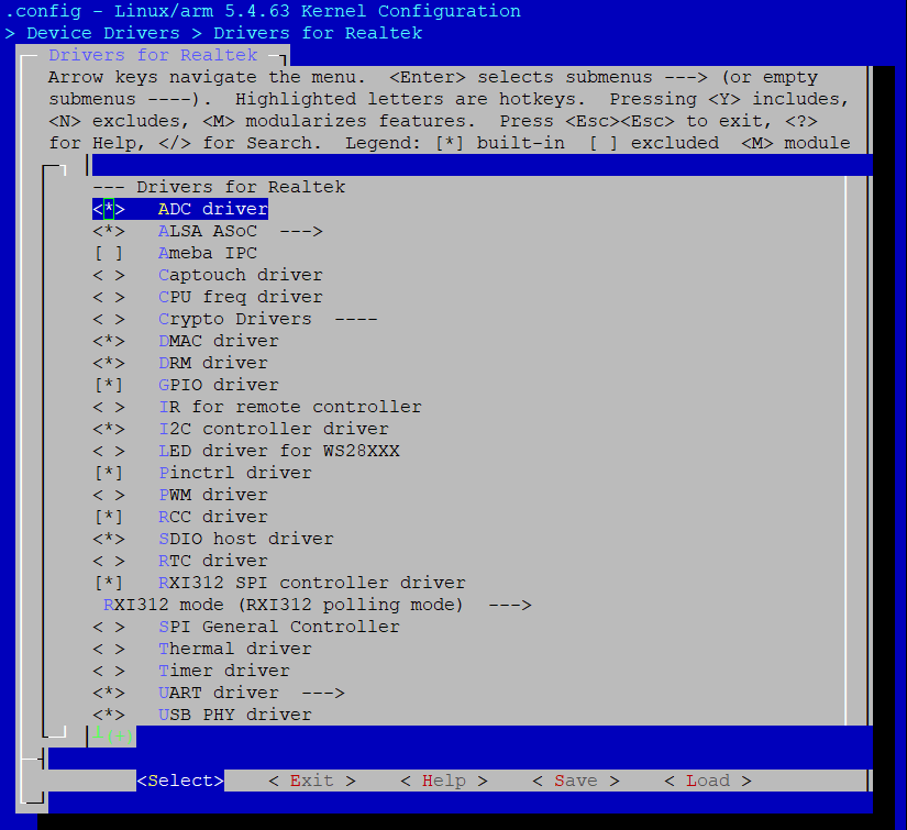
Build Configuration
Select for in order:

APIs
Official document: kernel API guide.
API for User Space
Sysfs Interface
Interfaces |
Introduction |
|---|---|
/sys/bus/iio/devices/iio:deviceX |
Configure and enable the IIO device. |
/sys/bus/iio/devices/triggerX |
Configure and enable the IIO trigger. |
For more API details, refer to <linux>/Documentation/ABI/testing/sysfs-bus-iio
ADC demo for user space locates at <test>/adc.
ADC Example
The demo is a simple example to read single ADC sample data.
Open ADC single raw read
sprintf(dev_name, "/sys/bus/iio/devices/iio:device0/in_voltage%d_raw", adc_ch);
fd = open(dev_name, O_RDONLY);
Single read ADC sample data
read(fd, buffer, 4);
Convert read data from char to int
value = atoi(buffer);
Value is the ADC single read data.
ADC Single Read Example
Get single raw sample data
cat /sys/bus/iio/devices/iio:device0/in_voltage0_raw
Get ADC offset
cat /sys/bus/iio/devices/iio:device0/in_voltage_offset
Get ADC scale
cat /sys/bus/iio/devices/iio:device0/in_voltage_scale
Get ADC differential offset
cat /sys/bus/iio/devices/iio:device0/in_voltage-voltage_offset
Get ADC differential scale
cat /sys/bus/iio/devices/iio:device0/in_voltage-voltage_scale
ADC Buffer Read Example
The steps to read ADC buffer are as follows:
Create trigger
echo 0 > /sys/devices/iio_sysfs_trigger/add_trigger
Note
0 is the index we need to assign to the trigger.
Assign trigger to device
echo sysfstrig0 > /sys/bus/iio/devices/iio:device0/trigger/ current_trigger
Note
Since we use 0 as the index, the trigger will be named sysfstrig0.
Enable scan elements: selecting the channel whose data values are pushed into the buffer
echo 1 > /sys/bus/iio/devices/iio:device0/scan_elements/in_voltage0_en
echo 1 > /sys/bus/iio/devices/iio:device0/scan_elements/in_voltage1_en
echo 1 > /sys/bus/iio/devices/iio:device0/scan_elements/in_voltage2_en
echo 1 > /sys/bus/iio/devices/iio:device0/scan_elements/in_voltage6_en
Set buffer size
echo 100 > /sys/bus/iio/devices/iio:device0/buffer/length
Enable buffer
echo 1 > /sys/bus/iio/devices/iio:device0/buffer/enable
Enable trigger: start acquisition
echo 1 > /sys/bus/iio/devices/trigger0/trigger_now
Disable buffer
echo 0 > /sys/bus/iio/devices/iio:device0/buffer/enable
Character Device
Interfaces |
Introduction |
|---|---|
/dev/iio:deviceX |
Access configured events and data. |
API for Kernel Space
Usage
Interfaces |
Introduction |
|---|---|
iio_read_channel_raw |
Read from a given channel. |
iio_convert_raw_to_processed |
Convert a raw value to a processed value. |
iio_read_channel_attribute |
Read values from the device attribute. |
iio_read_channel_offset |
Read the offset value for a channel. |
iio_read_channel_scale |
Read the scale value for a channel. |
iio_read_channel_processed |
Read processed value from a given channel. |
iio_get_channel_type |
Get the type of a channel. |
Configfs
Interfaces |
Introduction |
|---|---|
iio_sw_trigger_create |
Create a new trigger type. |
iio_sw_trigger_destroy |
Destroy a trigger type. |
iio_register_sw_trigger_type |
Register a new trigger type. |
iio_unregister_sw_trigger_type |
Unregister a trigger type. |
For more details of APIs, refer to:
<linux>/Documentation/ABI/testing/configfs-iio<linux>/Documentation/iio/iio_configfs.rst
Debugfs
Interfaces |
Introduction |
|---|---|
iio_debugfs_read_reg |
Read registers |
iio_debugfs_write_reg |
Write registers |
simple_open |
Open |