Introduction
Architecture
The SPI driver follows Linux framework: spi-dev.c, spi-mem.c, spi.c. The SPI software architecture is illustrated as below.

SPI software architecture
For more details on Linux SPI framework, refer to https://www.kernel.org/doc/html/v5.4/spi/spi-summary.html.
Implementation
The SPI driver is implemented as the following files:
Driver location |
Introduction |
|---|---|
<linux>/drivers/rtkdrivers/spi/Kconfig |
General SPI driver Kconifg |
<linux>/drivers/rtkdrivers/spi/Makefile |
General SPI driver Makefile |
<linux>/drivers/rtkdrivers/spi/spi-realtek-general.c |
General SPI functions. |
<linux>/drivers/rtkdrivers/spi/spi-realtek-general.h |
SPI related function declaration, macro definition, structure definition and the other header files quoted. |
Configuration
DTS Configuration
SPI DTS Property
spi0: spi0@0x400E8000 {
   compatible = "realtek,ameba-spi";
   rtk,spi-index = <0>;
   reg = <0x400E8000 0x100>,
   <0x41000000 0x30>; // reg base for spi role setting.
   interrupts = <GIC_SPI 40 IRQ_TYPE_LEVEL_HIGH>;
   clocks = <&rcc RTK_CKE_SPI0>;
   clock-names = "rtk_spi_clk";
   spi-max-frequency = <100000000>;
   spi-deactivate-delay = <0>;
   rtk,spi-for-kernel = <0>;
   rtk,spi-slave-mode = <0>;
   rtk,spi-dma-en = <0>;
   dmas = <&dma 16>,<&dma 17>;
   dma-names = "spi0-tx","spi0-rx";
   rtk,spi-master-poll-mode = <0>;
   rtk,spi-default-cs = <0>;
   rtk,max-cs-num = <2>;
   //only master mode set SPI_CS to GPIO, so spi0_pins only set SPI0_CLK, SPI0_MOSI and SPI0_MISO.
   rtk,spi-cs-gpios = <&gpiob 17 0>;
   status = "disabled";
};
The SPI DTS configurations of SPI are listed as below.
Property |
Description |
Configurable? |
|---|---|---|
compatible |
The description of SPI driver: |
No |
reg |
The hardware address and size for SPI device: The hardware address for SPI role setting: |
No |
interrupts |
The GIC number of SPI device: |
No |
clocks |
The clock of SPI device: |
No |
spi-max-frequency |
The maximum frequency for SPI device: |
No |
spi-deactivate-delay |
Delay time for SPI deactivate. Default: 0. |
Yes |
rtk,spi-for-kernel |
If spi controller is registered for kernel device, register board inifo in child-node probe. |
0/1 |
rtk,spi-slave-mode |
|
0/1 |
rtk,spi-dma-en |
If setting to 1,
dmas = <&dma 3> means the physical channel allocated to SPI.dma-names = "dma_spi" means the DMA channel name.If setting to 0, dmas and dma-names are useless parameters.
|
0/1 |
rtk,spi-master-poll-mode |
|
0/1 |
rtk,spi-default-cs |
If chip is not selected particularly, it will be the default chip. Default: 0. |
Yes |
rtk,max-cs-num |
The maximum number of chip. Default: 2. |
Yes |
rtk,spi-clk-divider |
Divide clock by this value. The lager value it is, the slower the SPI transfer will be. |
Yes |
rtk,spi-cs-gpios |
The gpio for SPI. |
Yes |
status |
Whether enable this device.
|
Yes |
SPI Pinmux
The pin assignments of SPI are listed as below.
SPI Device |
Port name |
Pin name |
pinctrl description |
|---|---|---|---|
SPI0 |
PA13 |
MOSI |
Shall add manually. |
SPI0 |
PA14 |
MISO |
Shall add manually. |
SPI0 |
PA15 |
SCLK |
Shall add manually. |
SPI0 |
PA26 |
CS |
Shall add manually. |
SPI0 |
PB4 |
MOSI |
Shall add manually. |
SPI0 |
PB3 |
MISO |
Shall add manually. |
SPI0 |
PB6 |
SCLK |
Shall add manually. |
SPI0 |
PB5 |
CS |
Shall add manually. |
SPI0 |
PB19 |
MOSI |
<&spi0_pins> |
SPI0 |
PB20 |
MISO |
<&spi0_pins> |
SPI0 |
PB18 |
SCLK |
<&spi0_pins> |
SPI0 |
PB17 |
CS |
<&spi0_pins> |
SPI0 |
PB29 |
MOSI |
Shall add manually. |
SPI0 |
PB30 |
MISO |
Shall add manually. |
SPI0 |
PB31 |
SCLK |
Shall add manually. |
SPI0 |
PC0 |
CS |
Shall add manually. |
SPI1 |
PA5 |
MOSI |
<&spi1_pins> |
SPI1 |
PA4 |
MISO |
<&spi1_pins> |
SPI1 |
PA3 |
SCLK |
<&spi1_pins> |
SPI1 |
PA2 |
CS |
<&spi1_pins> |
SPI1 |
PA9 |
MOSI |
Shall add manually. |
SPI1 |
PA10 |
MISO |
Shall add manually. |
SPI1 |
PA11 |
SCLK |
Shall add manually. |
SPI1 |
PA12 |
CS |
Shall add manually. |
SPI1 |
PA28 |
MOSI |
Shall add manually. |
SPI1 |
PA29 |
MISO |
Shall add manually. |
SPI1 |
PA26 |
SCLK |
Shall add manually. |
SPI1 |
PA27 |
CS |
Shall add manually. |
SPI1 |
PB10 |
MOSI |
Shall add manually. |
SPI1 |
PB11 |
MISO |
Shall add manually. |
SPI1 |
PB12 |
SCLK |
Shall add manually. |
SPI1 |
PB13 |
CS |
Shall add manually. |
SPI1 |
PB28 |
MOSI |
Shall add manually. |
SPI1 |
PB27 |
MISO |
Shall add manually. |
SPI1 |
PB25 |
SCLK |
Shall add manually. |
SPI1 |
PB26 |
CS |
Shall add manually. |
Pinmux can be revised according to specific conditions. Refer to pinctrl application node for more details.
SPI Group
The SPI group has two SPI devices named spi0 and spi1. The usage of these two SPI devices are the same.
aliases {
   spi0 = "/ocp/spi0@0x400E8000";
   spi1 = "/ocp/spi1@0x400E9000";
};
Build Configuration
Select :
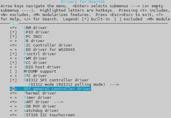
SPI general controller driver
APIs
APIs for User Space
Master Mode
The SPI interfaces for user space are provided by <linux>/drivers/spi/spi-dev.c.
Here are some commonly used APIs to control the SPI device:
Interfaces |
Introduction |
|---|---|
spidev_open |
Open an SPI device. |
spidev_release |
Release an SPI device. |
spidev_ioctl |
Configure SPI parameters, control read/write SPI data. |
spidev_write |
Call SPI driver to send a message. |
spidev_read |
Call SPI driver to read a message. |
Note
For more details, refer to https://www.kernel.org/doc/html/v5.4/spi/spidev.html.
The SPI demo for user space locates at <test>/spi.
Slave mode
The interface for SPI slave in user space is the same to master mode. To use SPI slave mode, just change master/slave mode in DTS described in DTS Configuration.
The usage of SPI slave mode and SPI master mode is the same. To use SPI slave mode, let rtk, spi-slave-mode = 1 in DTS described in DTS Configuration. Otherwise, set rtk, spi-slave-mode = 0 for master mode.
APIs for Kernel Space
Master Mode
The SPI interfaces for kernel space are described in <linux>/include/linux/spi/spi.h.
Interfaces |
Introduction |
|---|---|
spi_sync_transfer |
Synchronous SPI data transfer |
spi_write |
SPI synchronous write |
spi_read |
SPI synchronous read |
spi_write_then_read |
This copies txbuf and rxbuf data; for small transfers only! |
For more details, refer to https://www.kernel.org/doc/html/v5.4/spi/spidev.html.
Slave Mode
The interface for SPI slave in kernel space is the same to master mode. To use SPI slave mode, just change master/slave mode in DTS described in DTS Configuration.
The usage of SPI slave mode and SPI master mode is the same. To use SPI slave mode, let rtk, spi-slave-mode = 1 in DTS described in DTS Configuration. Otherwise, set rtk, spi-slave-mode = 0 for master mode.