Image Tool
Introduction
The Image Tool is the official image download tool developed by Realtek for Ameba series SoC. It can be used to download images to the Flash of the device through the interfaces below.
Ameba SoC |
Flash type |
Download interface |
|
|---|---|---|---|
UART |
USB |
||
RTL8730E |
NOR Flash |
√ |
√ |
NAND Flash |
X |
√ |
|
RTL8721Dx RTL8711Dx |
NOR Flash |
√ |
√ |
RTL8726EA RTL8713EC RTL8720EA RTL8710EC |
NOR Flash |
√ |
X |
The UI of Image Tool is shown below.
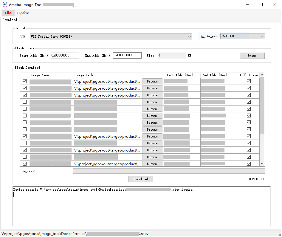
Image Tool UI
Environment Setup
Hardware Setup
The hardware setup for image download is shown below.
Software Setup
Environment Requirements: EX. WinXP, Win 7 or later, Microsoft .NET Framework 4.0.
Software location:
Image Tool:
{SDK}/tools/ameba/ImageTool/AmebaImageTool.exeDevice Profile Editor:
{SDK}/tools/ameba/DeviceProfileEditor/AmebaDeviceProfileEditor.exe
Device profiles:
{SDK}/tools/ameba/DeviceProfilesDevice profiles provide the necessary device information required for image download, with the naming rules:
<SoC name>_<OS type>_<Flash type>[_<Extra info>].rdev
Where:
- SoC name:
the name of Realtek Ameba SoC
- OS type:
FreeRTOS or Linux
- Flash type:
NOR or NAND
- Extra info:
extra information like Flash size, application, etc.
Note
{ImageTool}will be used for short of{SDK}/tools/ameba/ImageToolin the following sections.To download images through UART interface, the host driver for USB to UART adapter (e.g. PL2303GC) on the board shall be installed first, please find the exact driver from the official website of corresponding vendor of the USB to UART adapter.
For WinXP or Win7 only, install the USB driver
ImageTool/RtkUsbCdcAcmSetup.INFif there is a need to download images through USB interface.
Image Download
Download Images
For an empty chip, the following mandatory images shall be downloaded:
Ameba SoC |
Image name |
Description |
Mandatory? |
|---|---|---|---|
RTL8730E |
A: km4_boot_all.bin |
A slot: KM4 bootloader |
√ |
A: km0_km4_app.bin |
A slot: KM0/KM4 applications |
√ |
|
A: boot.img |
A slot: CA32 firmware package, including BL1, BL2, BL32 and BL33 |
√ |
|
B: km4_boot_all.bin |
B slot: KM4 bootloader |
X |
|
B: km0_km4_app.bin |
B slot: KM0/KM4 applications |
X |
|
B: boot.img |
B slot: CA32 firmware package, including BL1, BL2, BL32 and BL33 |
X |
|
A: vbmeta.img |
A slot: AP Linux meta data image, only for secure boot |
X |
|
B: vbmeta.img |
B slot: AP Linux meta data image, only for secure boot |
X |
|
A: xxx.dtb* |
A slot: AP Linux DTB (device tree blob) |
√ |
|
B: xxx.dtb* |
B slot: AP Linux DTB for recovery |
X |
|
A: kernel.img |
A slot: AP Linux kernel |
√ |
|
B: kernel.img |
B slot: AP Linux kernel |
X |
|
rootfs.img |
AP Linux rootfs binary |
√ |
|
userdata.img |
AP user data binary |
√ |
Note
For DTB image, Yocto will build all available DTS files in SDK into DTB images for users to select as required.
DTB image name |
Description |
|---|---|
rtl8730elh-va7-generic.dtb |
DTB for RTL8730ELH-VA7, with minimum features for customer design reference |
rtl8730elh-va7-full.dtb |
DTB for RTL8730ELH-VA7, with maximum features for development and demonstration |
rtl8730elh-va7-tests-xxx.dtb |
DTB for RTL8730ELH-VA7, with BSP test support, where xxx is:
|
rtl8730elh-va8-generic.dtb |
DTB for RTL8730ELH-VA8, with minimum features for customer design reference |
rtl8730elh-va8-full.dtb |
DTB for RTL8730ELH-VA8, with maximum features for development and demonstration |
rtl8730elh-va8-tests-xxx.dtb |
DTB for RTL8730ELH-VA8, with BSP test support, where xxx is:
|
Note
Refer to Linux DTS Pinmux Configurations for detailed information of DTS pinmux groups.
Download Steps
The image download steps are illustrated below:
Enter into download mode.
Push the button and keep it pressed.
Re-power on the device or press the button.
Release the button.
Now, the device goes into download mode and is ready to receive data.
Open Image Tool, click and select the proper device profile.
For RTL8730ELH-VA7, select
AmebaSmart_Linux_NAND_128MB.rdevFor RTL8730ELH-VA8, select
AmebaSmart_Linux_NAND_256MB.rdev
Select the corresponding serial port, and the baud rate will be ignored for USB download interface.
Click the button to select the images to be programmed.
Note
Flash layout is allowed to be changed via Image Tool if indeed necessary. However, to formally change the Flash layout, it is suggested to use
Device Profile Editorother thanImage Tooland the Flash layout in SDK shall be changed accordingly. Refer to Section Modifying Device Profile for details.Click the button to start. The progress bar will show the download progress of each image and the log widget will show the operation status.
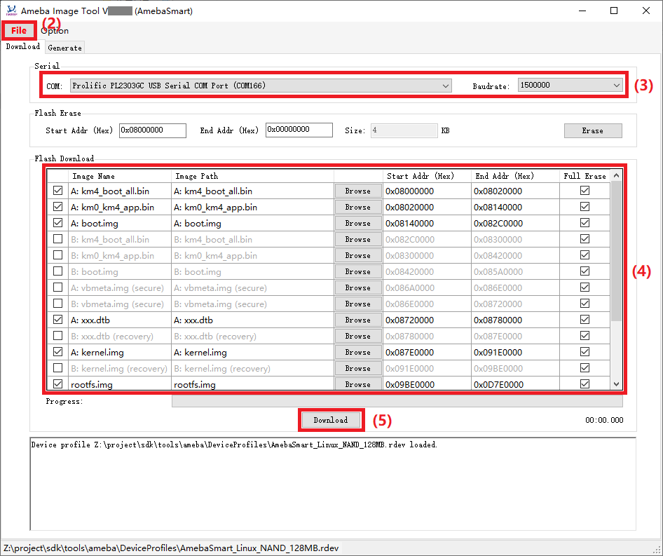
Image download operation
Flash Erase
Steps to erase Flash are illustrated below:
Enter into download mode as introduced above.
Open Image Tool, click and select the proper device profile.
Select the corresponding serial port and baud rate.
Note
The baud rate will be ignored for USB download interface.
Input erase start address.
For NOR Flash, the value shall be 4KB aligned.
For NAND Flash, the value shall be aligned to block size.
Note
Refer to the datasheet of the corresponding NAND Flash for block size, normally 128KB.
Input erase size.
For NOR Flash, the value shall be cast to a multiple of 4KB.
For NAND Flash, the value shall be cast to a multiple of block size.
Note
Refer to the datasheet of the corresponding NAND Flash for block size, normally 128KB.
Click the button, and erase operation begins.
You would get the operation result from the log window.
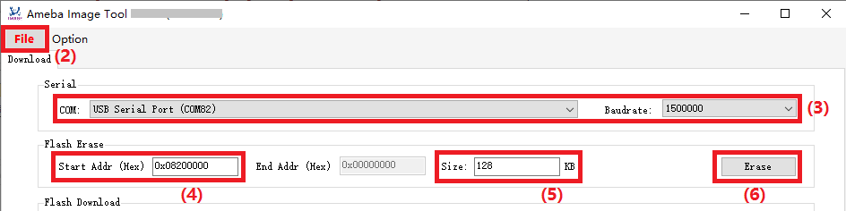
NOR Flash erase operation
Note
No need to erase Flash manually before image download since Flash will be automatically erased during image download process.
If Flash block protection is detected at Step 6, refer to Section Flash Block Protection Process for details.
Flash Register Access
This function is for internal usage only, used to read/write Flash status/feature registers.
Caution
Any Flash register operations, especially write operations, shall refer to the datasheet of the Flash; otherwise, it may cause irreversible damage to the Flash.
Common pre-steps to access Flash register are illustrated below:
Make sure the Image Tool is closed.
Enter expert mode by editing
<ImageTool>/Setting.json, and set ExpertMode value to none-zero integer (such as 1).Enter into download mode as introduced above.
Open Image Tool, click and select the proper device profile.
Select the corresponding serial port and baud rate.
NOR Flash Register Access
Besides the common pre-steps, click and select item to lunch the NOR Flash Register Access dialog for further operations:
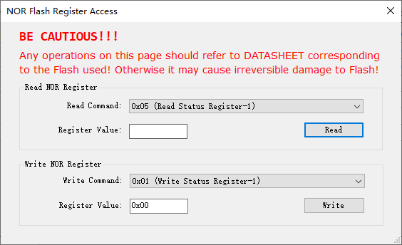
NOR Flash Register Access dialog
Read NOR Flash Register
After the common pre-steps, next steps to read NOR Flash register:
Select the read command to read specific register.
Click the button, the register value will show up in the Register Value text box.
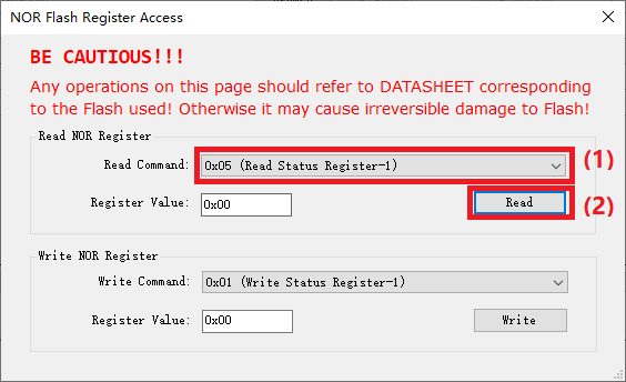
Read NOR Flash register operation
Write NOR Flash Register
After the common pre-steps, next steps to write NOR Flash register:
Select the write command to write specific register.
Input the register value.
Click the button.
Read back the register value for verification, refer to Section Read NOR Flash Register.
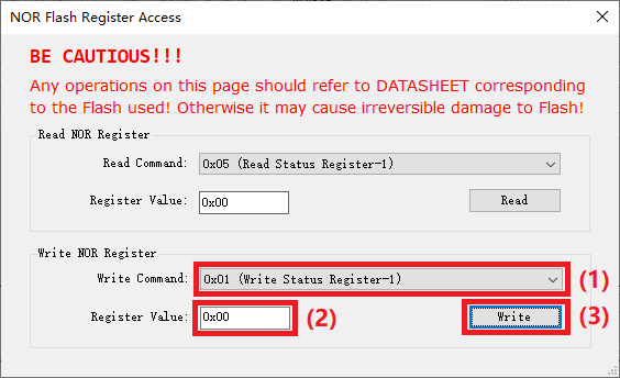
Write NOR Flash register operation
Flash Block Protection Process
During image download or Flash Erase operation, if Flash block protection configuration is detected on the device, Image Tool will pop up a dialog to guide user for the follow-up actions.
For NOR Flash, only Flash type and protection register value will be shown.
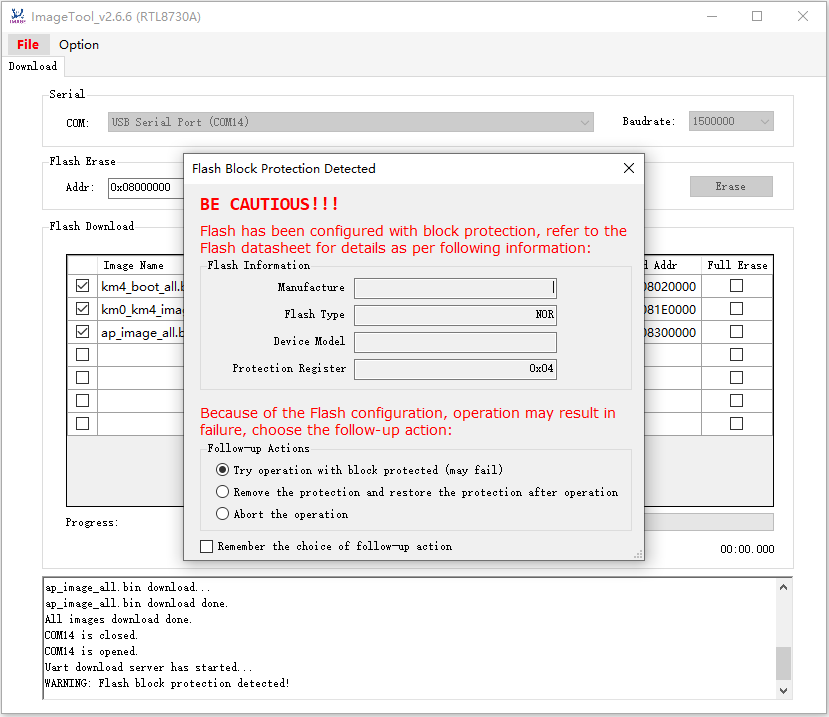
Flash block protection detected dialog for NOR Flash
The following follow-up actions are provided for users to choose:
Try operation with block protected (may fail)
Remove the protection and restore the protection after operation
Abort the operation
Additionally, user can check the check box to remember the choice for further operations, and uncheck to forget the remembered choice.
Modifying Device Profile
Steps to modify an existing device profile are listed below:
Launch Device Profile Editor.
Click Open button to load an existing device profile.
Change the configuration of
Flash Layoutas required.Image Name: the image name built by SDKStart Address: start address in hex format. For NAND Flash, the value shall be aligned to block size.End Address: end address in hex format. For NAND Flash, the value shall be aligned to block size and the partition size shall be a multiple of block size with proper percent of spare blocks (at least one) for bad block management.Full Erase: flag indicating ImageTool to erase the entire partition or not before image downloadChecked: full erase, normally for file system partitions; for NAND Flash, all the partitions will be checked as default and not allowed to uncheck.
Unchecked: not full erase, only the actual size of the image file will be erased, only for NOR Flash non-file-system partitions.
Mandatory: flag indicating ImageTool to enable the partition to download as default.Checked: mandatory partition, enabled as default.
Unchecked: optional partition, disabled as default.
Description: the description text to describe the image, this information will be used as mouse hover tips for images.
Click Save button to overwrite the existing device profile or click Save As button to save the modified device profile to a new file.
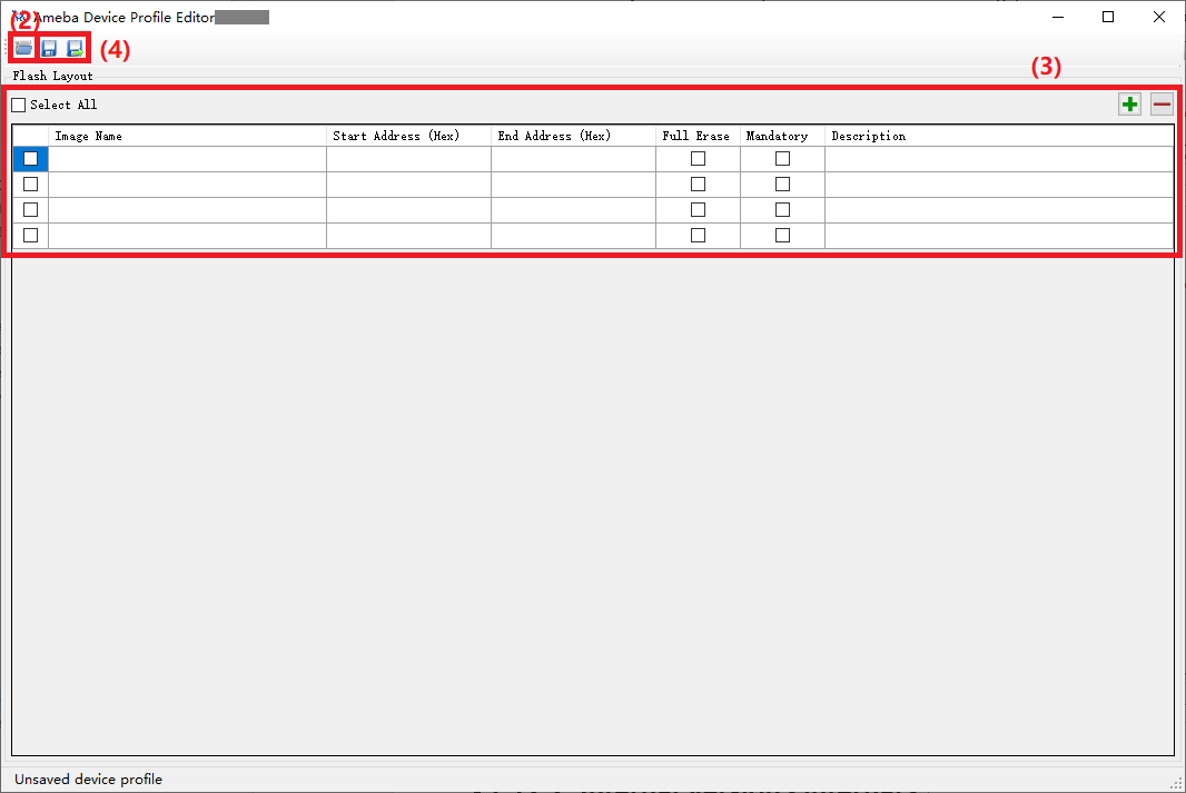
Editting an existing device profile