Pinmux Tool
Introduction
The Pinmux Tool is the official pinmux and clock adjustment tool developed by Realtek for Ameba series SoC, which is used to adjust chip’s pinmux and clock.
The UI of Pinmux Tool is shown below:
Environment Setup
Software setup:
Environment Requirements: EX. WinXP, Win 7 or later, Microsoft .NET Framework 4.0.
Software location:
{SDK}\tools\Ameba\PinmuxTool\AmebaPinmuxTool.exe
Pinmux Adjustment
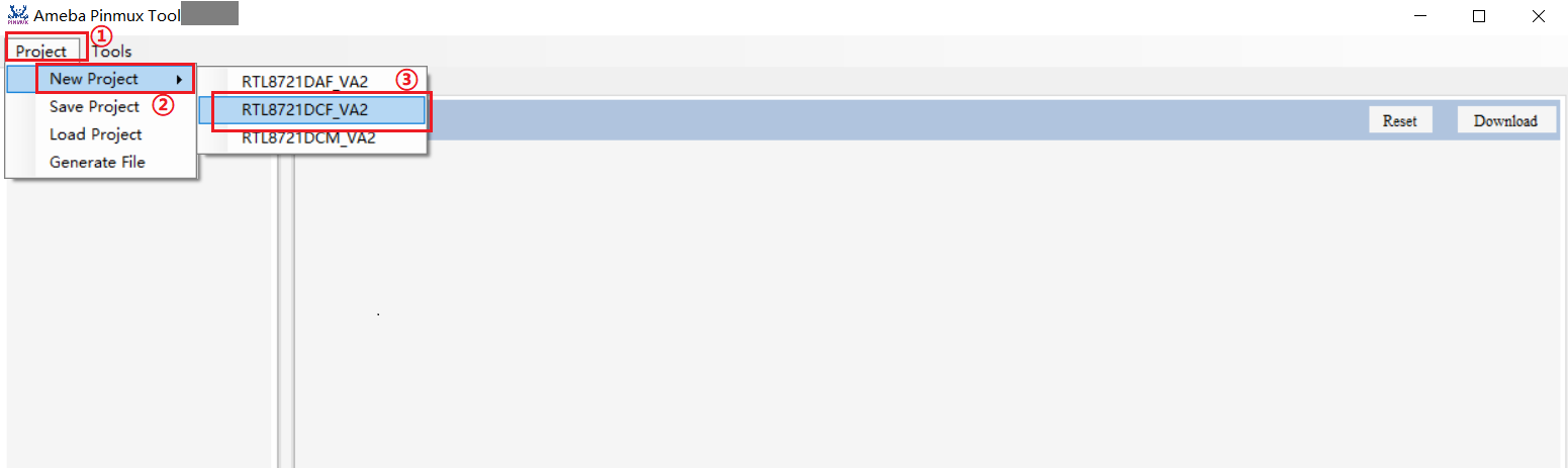
Project Creation
The steps of creating a new project are illustrated below:
Click Project button in menu bar.
Click New Project button.
Choose the chip type
Pin Assignment
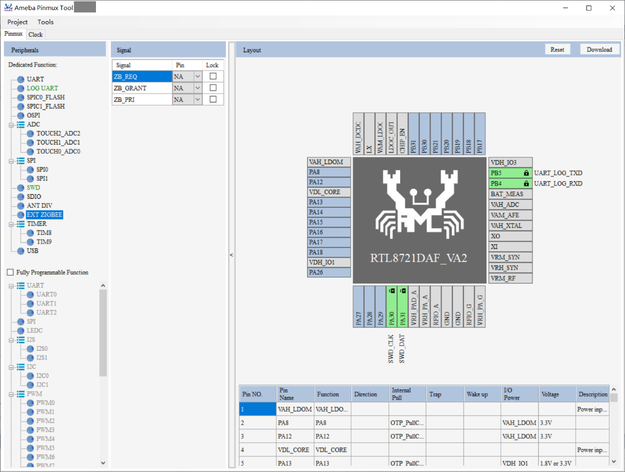
The Pinmux page contains three parts:
Peripherals: shows all peripherals of the chip, containingDedicated FunctionandFully Programmable Function.Signal: shows specific peripheral’s signal, used to assign pin for signal.Layout: shows the chip’s pinout.
The steps of assigning pin to peripheral are illustrated below:
Choose specific peripheral in
Peripherals.Assigning pin to required signals in
Signal.Layoutwill update pinout synchronously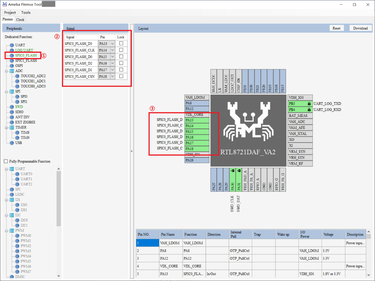
Note
When both dedicated function and fully programmable function can be configured as one function, using of dedicated function can achieve a higher speed.
When peripherals need be used in group, select one of the functions and the remaining functions will be assigned automatically.
Function Assignment
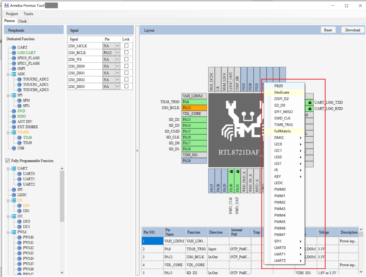
The Layout page shows chip’s pinout. GPIO pin’s color is blue, which can be assigned to different functions. The steps of assigning function to pin are illustrated below:
Select a pin.
Click the pin to show all functions it can be assigned to.
Select the required function.
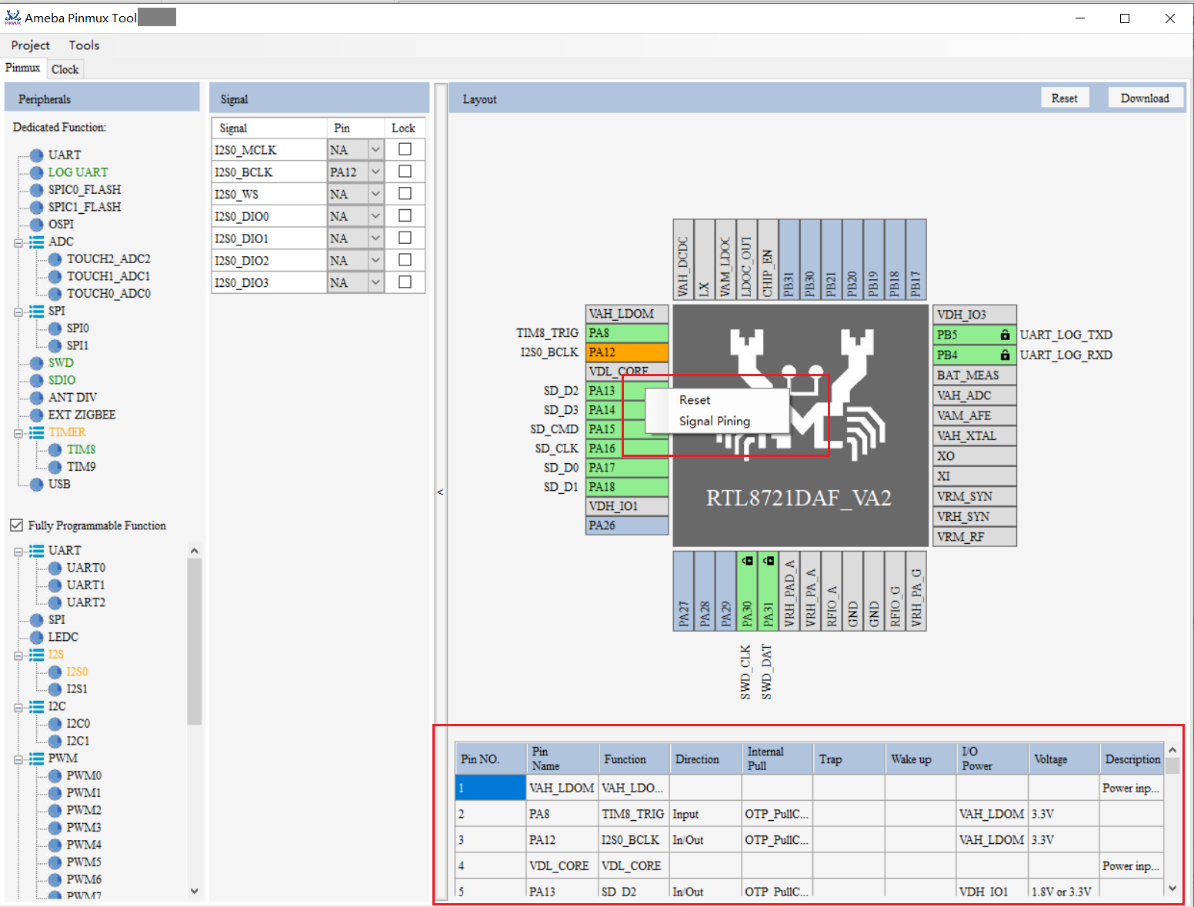
Right-click to reset pin or lock function in pin.
After function assignment, the color of pin will turn green or orange:
Green: means all functions of this peripheral are assigned.
Orange: means not all functions of this peripheral are assigned.
The pinout table below will dynamically update the information of each pin.
File Generation
After assigning pinmux, a corresponding table can be generated, steps are illustrated below:
Click Project button.
Click Generate File button.
Select file path and enter file name
The file will be generated in the corresponding directory with the format .csv.
Project Saving and Loading
The steps of saving project are illustrated below:
Click Project button.
Click Save Project button.
Select file path and enter file name.
The file will be generated in the corresponding directory with the format .pmx.
The steps of loading project steps are illustrated below:
Click Project button.
Click Save Project button.
Choose file.
Tool will update UI.
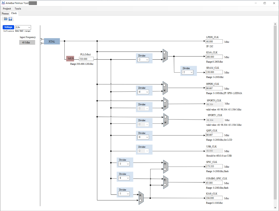
Clock
Clock Adjustment
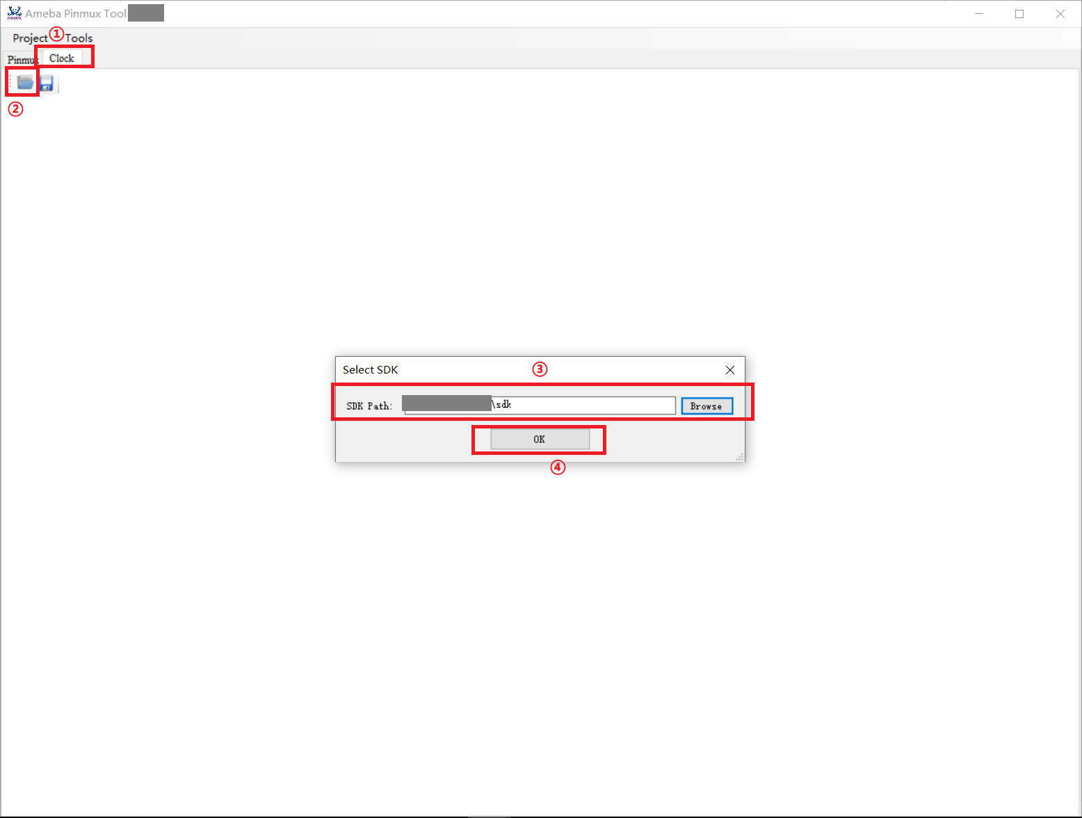
The Clock function is used to adjust chip’s clock information. The adjustment steps are illustrated below:
Choose chip type in pinmux page.
Click Clock button.
Click open file icon.
Choose SDK file path.
Click OK button.
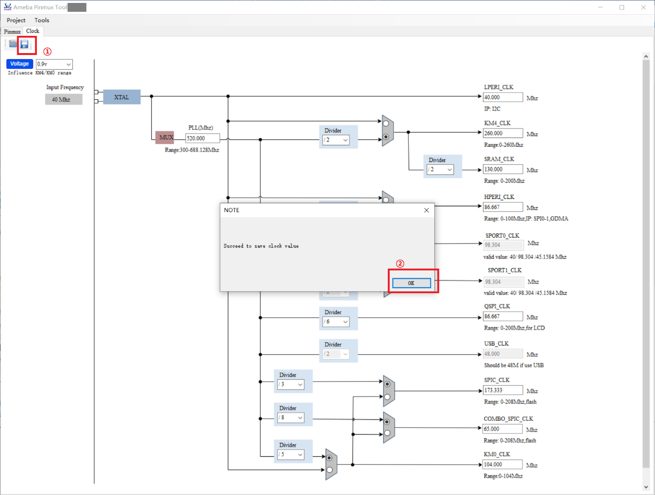
Configuration Saving
After completing the configuration of clock, click the save icon in menu bar to save it.
Modifications will be saved to the file: {SDK}\component\soc\amebadplus\usrcfg\ameba_bootcfg.c