How to Use AT Command with SPI
Overview
In Host Control Mode, when high performance and throughput are required, the SPI peripheral interface can be used for data transfer.
The host device acts as the SPI Master, and the AT device acts as the SPI Slave. The two parties exchange AT command data through the SPI protocol and a specific communication format.
Refer to Host Control Mode Configuration to set up the SPI peripheral interface.
Pin Description
The SPI peripheral interface requires 7 pins:
SPI pins: MOSI, MISO, CLK, CS (4 pins).
Two synchronization GPIO pins:
master_sync_pinandslave_sync_pin.GND (ground).
SPI transfers are initiated by the Master. The Slave cannot initiate data transmission. When the Master initiates a transfer, it must ensure the Slave has already invoked the receive API and is ready for reception; otherwise, data loss may occur.
The two synchronization GPIO pins resolve this issue:
master_sync_pin: The Master pulls this pin low to notify the AT device to prepare for reception before sending data.slave_sync_pin: The AT device pulls this pin low to notify the Master that it is ready to receive data or has AT messages to actively send.
Refer to AT Configuration Modification to modify these pins.
Host Reference Example
https://github.com/Ameba-AIoT/ameba-rtos/tree/master/component/example/atcmd_host/atcmd_spi_master
The file example_atcmd_spi_master.c demonstrates SPI communication between a Master and Slave. It is recommended to run this example before formal development to validate the connection and configuration.
The code includes a UART task for receiving AT commands and printing AT responses. The overall data flow diagram is shown below:

Note
For better performance optimization, each data interaction between the Host and AT module uses a fixed length of 16384 Bytes. Excess data beyond the valid payload will be ignored.
Communication Format
Data transmitted via SPI AT commands must follow this format:
Magic Number (2 bytes) |
Data Len (2 bytes) |
Data (Data Len bytes) |
Checksum (4 bytes) |
Where:
- Magic Number:
ATin ASCII code.- Data Len:
Data length in bytes.
- Checksum:
CRC32 checksum of all except Checksum field.
Interaction Flow
The SPI AT command interaction consists of two processes:
Host sends AT command
Slave returns AT response
Host Sending AT Command
The Host pulls the
master_sync_pinpin low to initiate a data transfer request.The Slave detects the request via GPIO interrupt, prepares for reception, and pulls the
slave_sync_pinpin high to notify the Host.The Host starts SPI data transfer. After completion, both sides reset the synchronization pins.

Slave Returning AT Response
The Slave pulls the
slave_sync_pinpin high to notify the Host that it has an AT response ready.The Host initiates SPI data reception. After transfer completion, the Slave resets the synchronization pin.

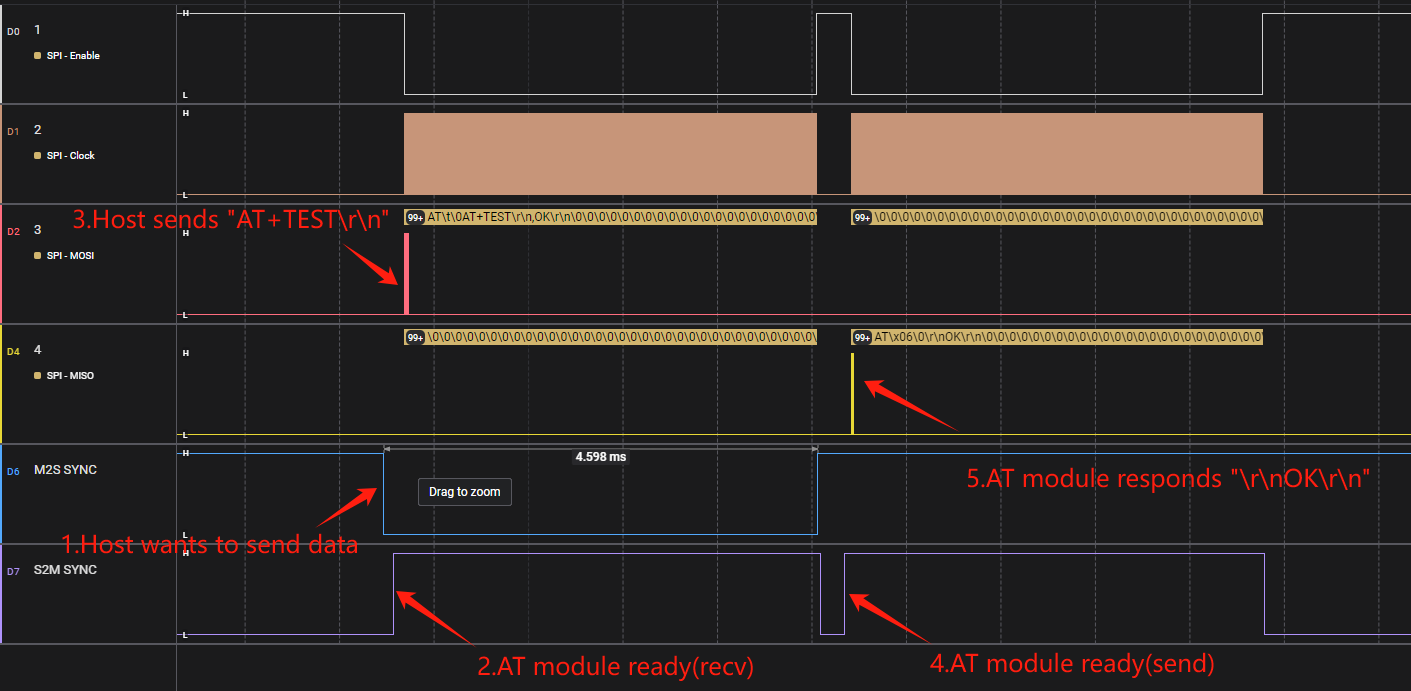
Interaction Timing
The interaction timing of SPI AT command is illustrated below:
Communication Rate
To test the SPI link rate, refer to AT+TEST command.
Note
When using a high SPI clock frequency, increasing the fixed packet length can improve overall throughput.