Captouch Test Tool
Introduction
Cap Test Tool is the official Cap-Touch calibration tool developed by Realtek for Ameba series SoC. By communication with corresponding Cap-Touch test daemon on device via UART port, Cap Test Tool can calibrate the general and channel-specific Cap-Touch configurations.
The UI of Cap Test Tool is shown below.
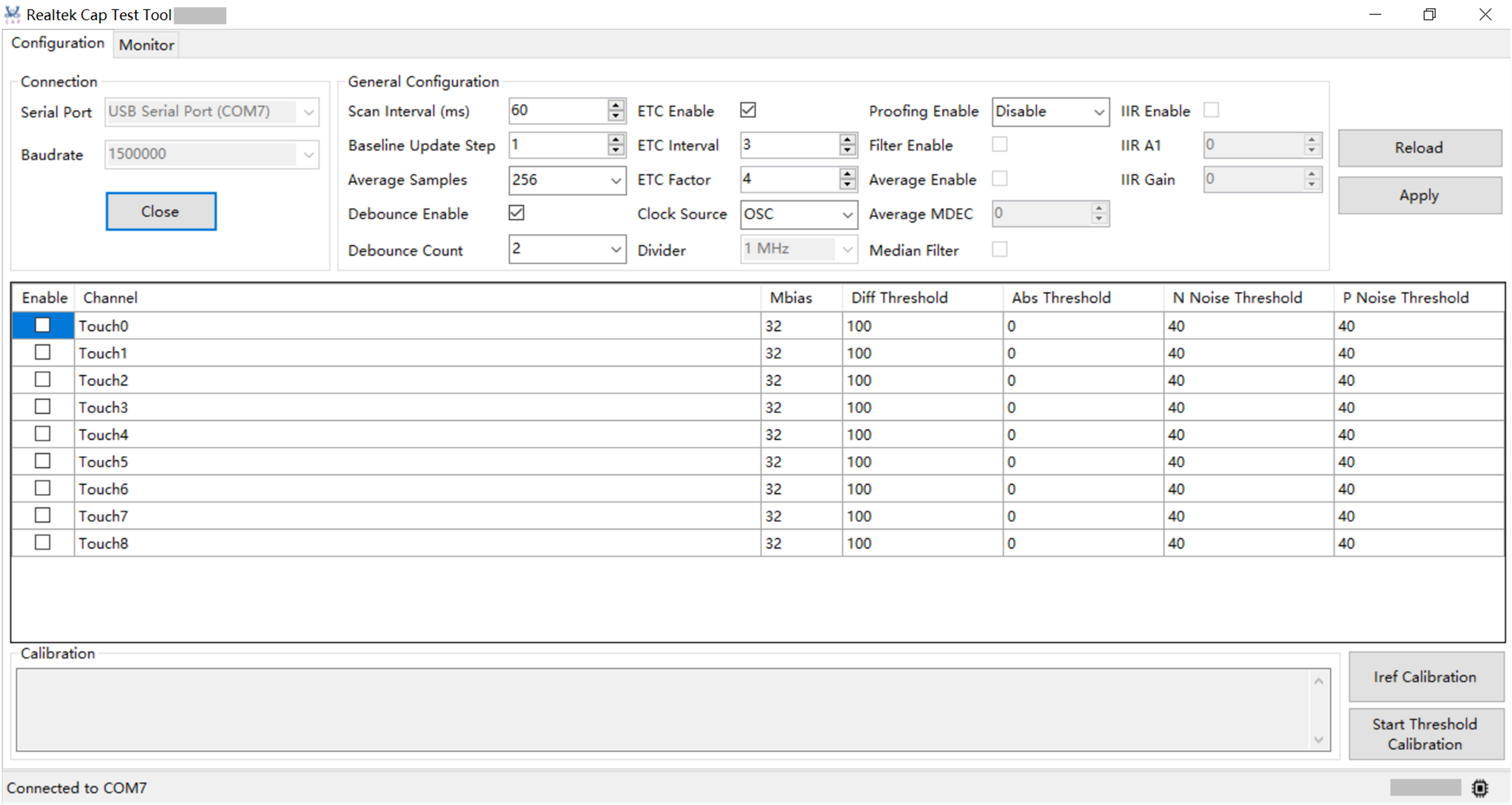
Cap Test Tool UI
Environment Setup
Hardware Setup
The hardware setup is shown below.

Hardware setup
The default UART pins of different ICs for Cap-Touch are listed below:
Ameba SoC |
Default UART pins |
|---|---|
RTL8730E |
|
RTL8726EA
RTL8713EC
RTL8720EA
RTL8710EC
|
|
RTL8721Dx
RTL8711Dx
|
|
Software Setup
Host:
Environment requirements: EX. WinXP, Win 7 or later, Microsoft .NET Framework 4.0.
Software location:
{SDK}/tools/ameba/CapTestTool/CapTestTool.exe
Device:
Build images with cap_test_daemon example, refer to
{SDK}/component/example/cap_test_daemon/readme.txtfor details.
Principle
The capacitance capture circuit adopts constant current source charging and ADC sampling voltage, the simple diagram is shown below.
The constant current source I_mbias can be configured to charge the Vt net periodically, and there are parasitic capacitance Cp and touch capacitance Ctouch on the Vt net.
Usually for a well-designed PCB, the ratio of Ctouch to Cp is about 1:10 to 1:20, so in fact, the proportion of useful signals is very small.
The ADC synchronized with the charge and discharge controller samples the voltage of the Vt net and collects the maximum voltage at the end of the charge.
ADC converts analog voltage into digital code identified by MCU for subsequent processing.

Simple diagram

Waveform of Vt
As shown below, the Cap-Touch Controller (CTC) scan period consists of active time and sleep time, which can be configured individually for different applications.

Scan period diagram
With the disturbance of the surrounding environment, such as temperature, moisture, overlay, or other slight environmental noise, sensor capacitance change is caused. ETC module is designed to track environmental changes and make calibrations.
ETC system tracks the capacitance change and updates the baseline and touch-threshold parameters based on the ETC algorithm periodically. ETC scan interval can be configured by ETC Interval parameter. Users can decide how many intervals of scan periods they need to update the baseline in order to save power consumption.
Manual tuning of ETC parameters is also supported to meet different environments or special applications. Increasing the baseline update step can accelerate the speed of baseline updating. Weighting factor is used as the baseline update principle in the judgment logic module. For each ETC scan period, if the noise difference (baseline - signal) is larger than the factor, the baseline will increase. If the noise difference (baseline ─ signal) is smaller than the factor, the baseline will decrease.
Configuration
Parameters
Parameter |
Value |
Comment |
|---|---|---|
Scan Interval |
0~4095ms |
The sleep time of channel after the sensor scanning and data processing. Recommended sleep time is 20~500ms for better response time. |
Average Samples |
4/8/16/32/64/128/256/512 |
The sample number of raw data which is used to capture ADC for best accuracy and noise immunity. |
Debounce Enable |
0/1 |
The debounce feature avoids false triggering of sensors caused by noise spikes or system glitches.
|
Debounce Count |
2/3/4/5 |
The shorter debounce times, the faster device responds to a sensor touch events. |
ETC Enable |
0/1 |
Environment tracking and calibration.
|
ETC Interval |
0~127 |
The count of scan intervals to do ETC update. Scan period contains active time and scan interval. ETC_update_interval=(scan_inteval+1)*scan_period |
Baseline Update Step |
0~15 |
Baseline update step (2^n) in ETC update principle. Use this parameter to configure baseline update step. |
ETC Factor |
0~15 |
Factor weight (2^n) for baseline update principle. For each ETC scan period, if the noise difference (baseline-signal) is larger than Factor, the baseline increases. If the noise difference (baseline-signal) is less than Factor, the baseline decreases. |
Clock Source |
|
Sample clock:
|
Divider |
1MHz/500KHz/250KHz/167KHz/125KHz/62.5KHz/31.25KHz |
Sample clock for XTAL 2MHz Divider: max. sample clock is 1MHz, charge time t = 0.us. |
Proofing Enable |
Disabled |
|
Filter Enable |
|
|
Average Enable |
|
|
Average MDEC |
RTL8721Dx/RTL8711Dx: 0~32767 |
|
Median Filter |
|
|
IIR Enable |
|
|
IIR A1 |
RTL8721Dx/RTL8711Dx: 0~65535 |
|
IIR Gain |
RTL8721Dx/RTL8711Dx: 0~65535 |
|
Parameter |
Value |
Description |
|---|---|---|
Mbias |
|
Sensitivity setting for each channel. 1 LSB = 0.25uA. Different register bit map:
|
Diff Threshold |
0~4095 |
Difference threshold judgement mode operates when ETC function is enabled. Compare the average sample data with the difference threshold to judge touch or proximity. |
Abs Threshold |
0~4095 |
Absolute threshold judgement mode operates when ETC function is disabled. Compare the average sample data with the absolute threshold to judge touch or proximity. |
N Noise Threshold |
0~4095 |
Raw data of the maximum capacitance change caused by the environmental change. |
P Noise Threshold |
0~4095 |
Raw data of the maximum capacitance change caused by the environmental change. |
Sample Data |
0~4095 |
Real finger touch voltage. Also named average data. |
Baseline Data |
0~4095 |
The reference voltage. Active when ETC enabled. |
Diff Data |
-4095~4095 |
Difference data between average data (sample data) and baseline data. Active when ETC enabled. Diff Data = Baseline Data - Average Data |
SNR |
SNR monitor operates effectively during project development or MP. \(SNR= |Diff Data (touch signal)|/|Noise (peak-to-peak)|\) |
Reload Configuration
Make sure the device is connected.
Go to the Configuration tab.
Click the Reload button.
Note
The configuration will be auto-reloaded when Open button is clicked.
When you click Apply or Reload button, both general configurations and channel configurations will take effect simultaneously.
Apply Configuration
Make sure device is connected.
Go to the
Configurationtab.Change the value of parameters listed in Table General configuration and Channel configuration.
Click the Apply button.
Calibration
Using tool to adjust Iref and threshold, it is more convenient to adjust the parameters that meet the performance requirements.
Note
The same set of hardware circuit corresponds to the same set of parameter values. After the hardware circuit is replaced, the calibration parameter values need to be reset.
Cap Test Tool is used as a tool to improve the debugging speed in the development stage, after the parameter calibration of a model product, users need to fill in the suggested parameters given by tool in the SDK code, so as to solidify a set of parameters in FLASH to realize batch operation.
Operational details of the SDK can be provided in the application note.
Iref Calibration
Iref determines the sensitivity.
Theoretically, the larger Iref is, the higher the sensitivity will be. But too high Iref will cause the charging voltage to exceed the measurement range of ADC, so a reasonable Iref should meet the following principles:
The sampling value of the untouched state accounts for about 80% of the ADC maximum range. Because the ADC resolution is 12 bits, and the maximum range number code is 4095, it is safer that the sampling value of the untouched state is set at about 3300.
Note
The value filled in the register is only used for tool. When the IC is powered off, the register will be cleared. Therefore, if you want to save the calibration result value, you need to fill the result parameters (Mbias) into the SDK.
The calibration process of Iref is integrated in the tool, and the user is only required to complete the following calibration process:
Make sure device is connected.
Go to the
Configurationtab.Select the checkbox of channels which need to be enabled.
Click the
Iref Calibrationbutton.Caution
Don’t touch Cap-Touch pins during Iref calibration process.
Observe the logs and wait the process to complete.
Both mbias and baseline will be calibrated in device, and mbias will be updated in Cap Test Tool.
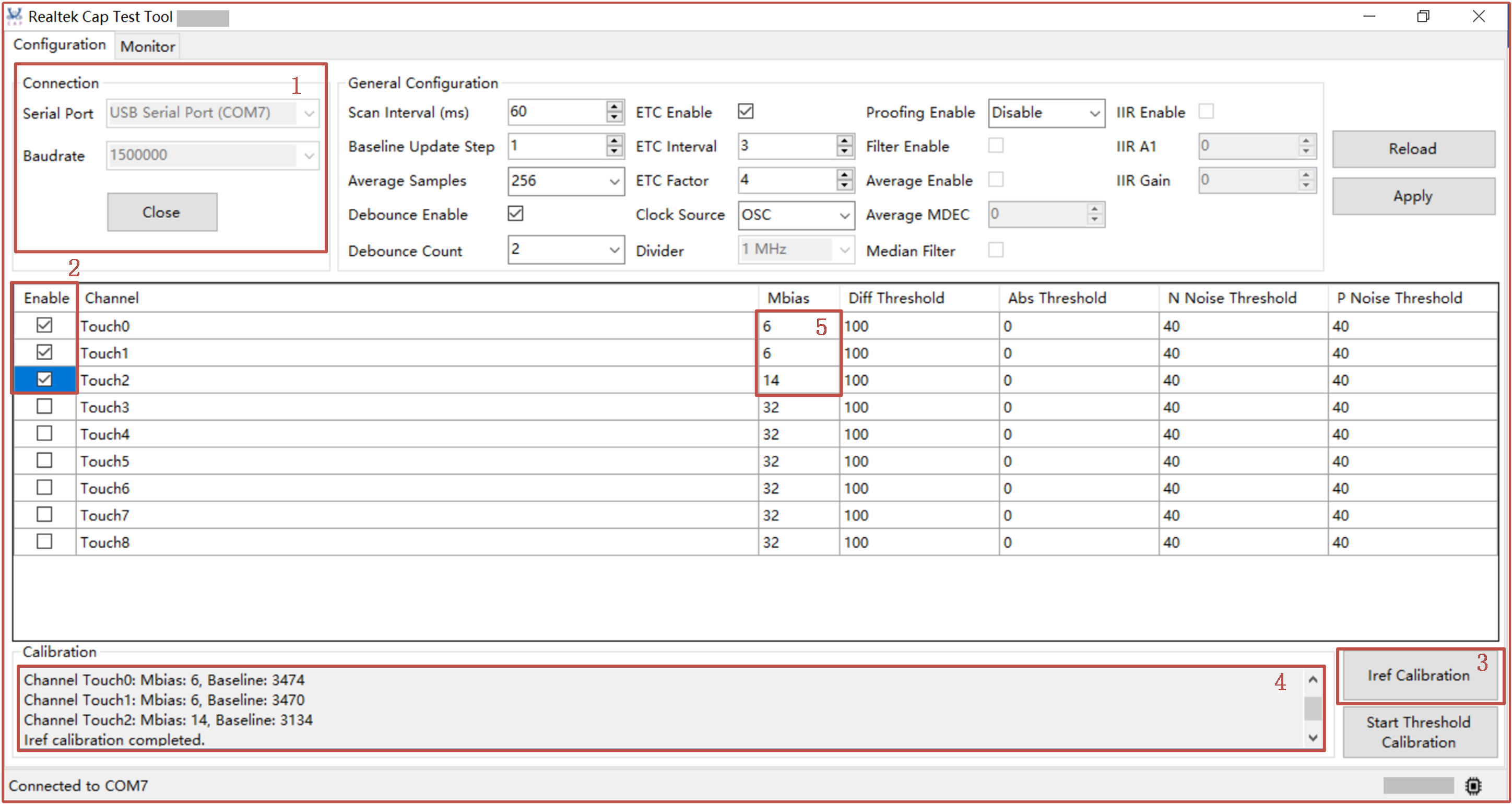
Iref calibration operation
Threshold Calibration
The threshold (Diff threshold) determines the reliability and flexibility of the touch operation. Too high threshold may cause the touch to be accurately identified, and too low threshold may cause false trigger operation. Therefore, a reasonable threshold should be personalized according to the test results of the actual circuit. Generally, it is recommended to set the threshold at 80% of the touch value.
Calibration program adopts the way of touch with manual operation, because the tool does not know the size of the touch signal in advance, the user needs to make 2 or 5 standard touches operation after clicking the button to start the task of calibrating the threshold. The task will record the average touch, and after the user clicks the button again to end the task, a reasonable threshold will be automatically filled in the register.
The threshold also includes the noise threshold, which is used to limit the noise range and realize the noise tracking and filtering of the algorithm, usually without too much attention from the user. The user only needs to divide the calibrated Diff threshold by 2 and fill in the SDK as N Noise threshold and P Noise threshold respectively.
The absolute value threshold is the debugging function, which the user does not need to pay attention to, and this parameter limits the touch behavior when the ETC function is disabled.
Note
The value filled in the register is only used for tool. When the IC is powered off, the register will be cleared. Therefore, if you want to save the calibration result value, you need to fill the result parameters (Diff threshold, N Noise threshold and P Noise threshold) into the SDK.
Make sure the device is connected.
Go to the
Configurationtab.Select the checkbox of channels which need to be enabled.
Click the
Start Threshold Calibrationbutton.The tool starts to print logs.
Touch channels.
If you want to observe the signals, continue Step 6; otherwise, jump to Step 8.
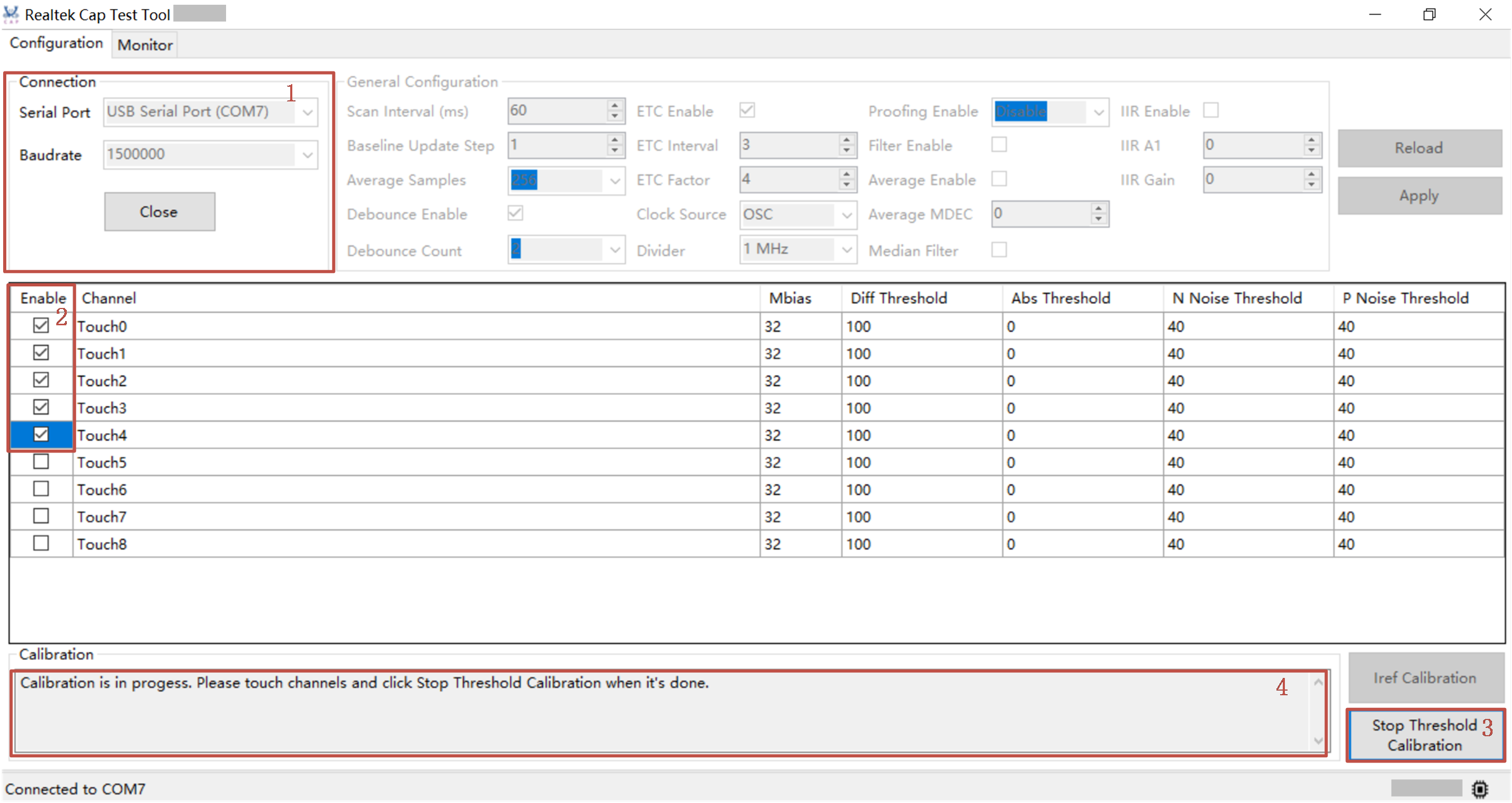
Threshold calibration operation (before calibration)
Switch to the
Monitortab.It only shows
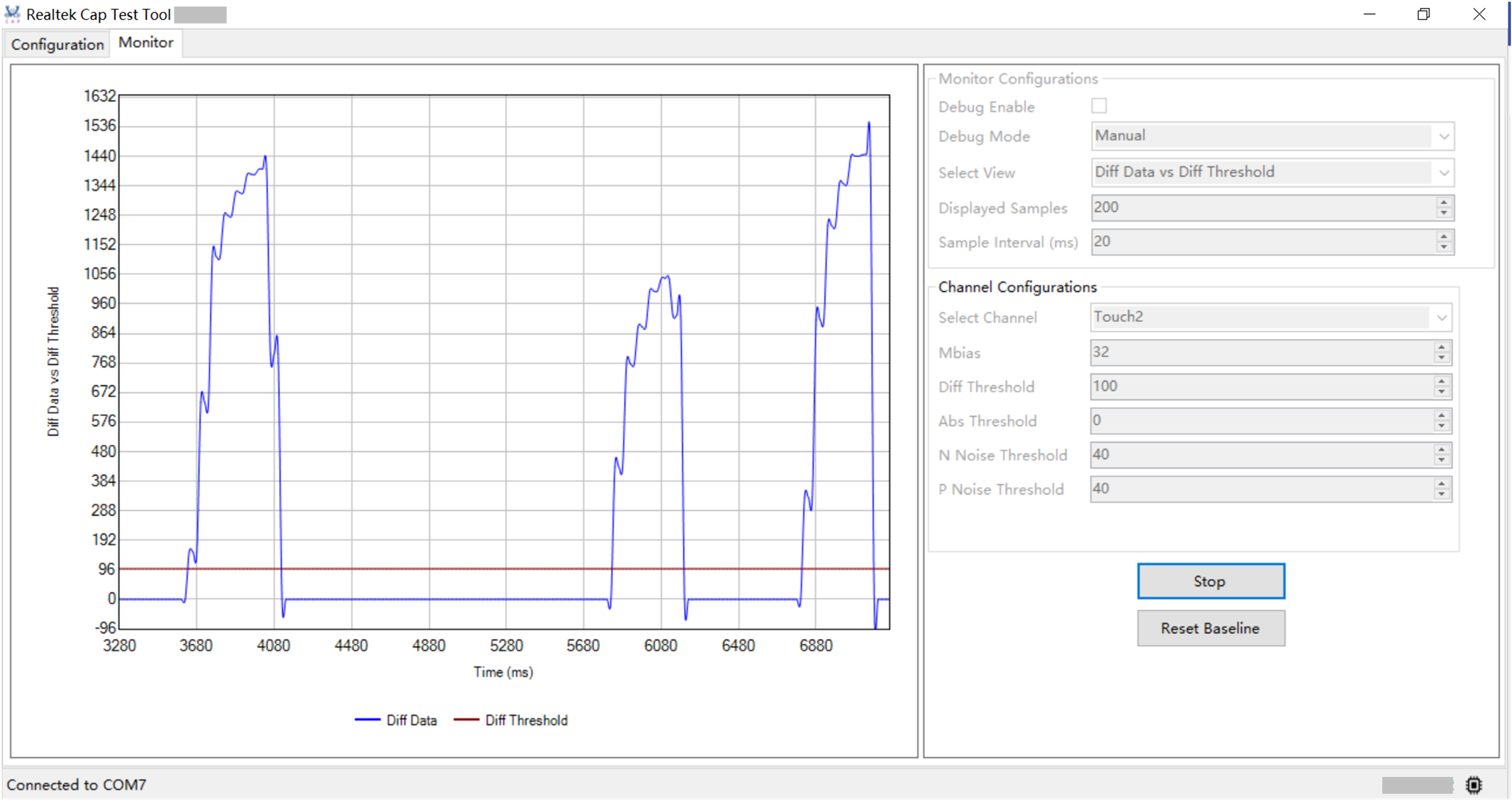
Diff Data vs Diff Thresholdview. Change theSelect Channel(s)box to switch channels.Note
Diff threshold will be set to the value of 80% of max. diff data.
Noise threshold will be set to the value of 40% of max. diff data.
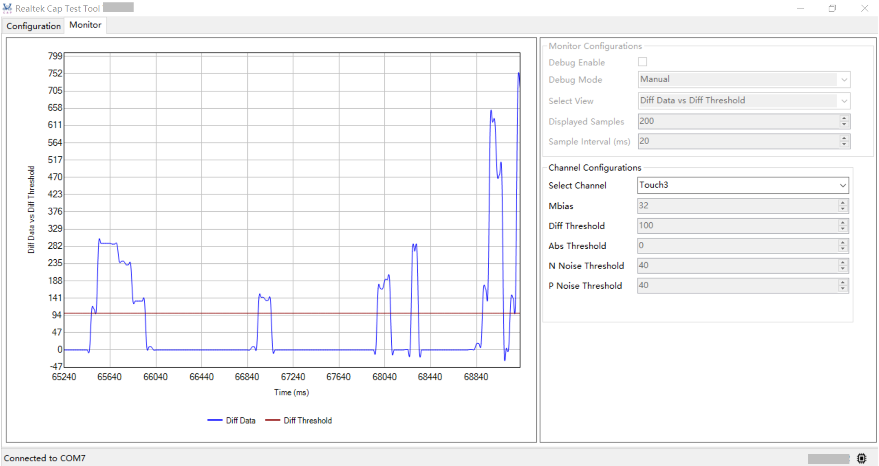
Threshold calibration operation (in calibration)
Switch to the
Configurationtab.
Click the
Stop Threshold Calibrationbutton.Cap Test Tool calculates diff threshold and noise threshold, prints log and updates values in cells.
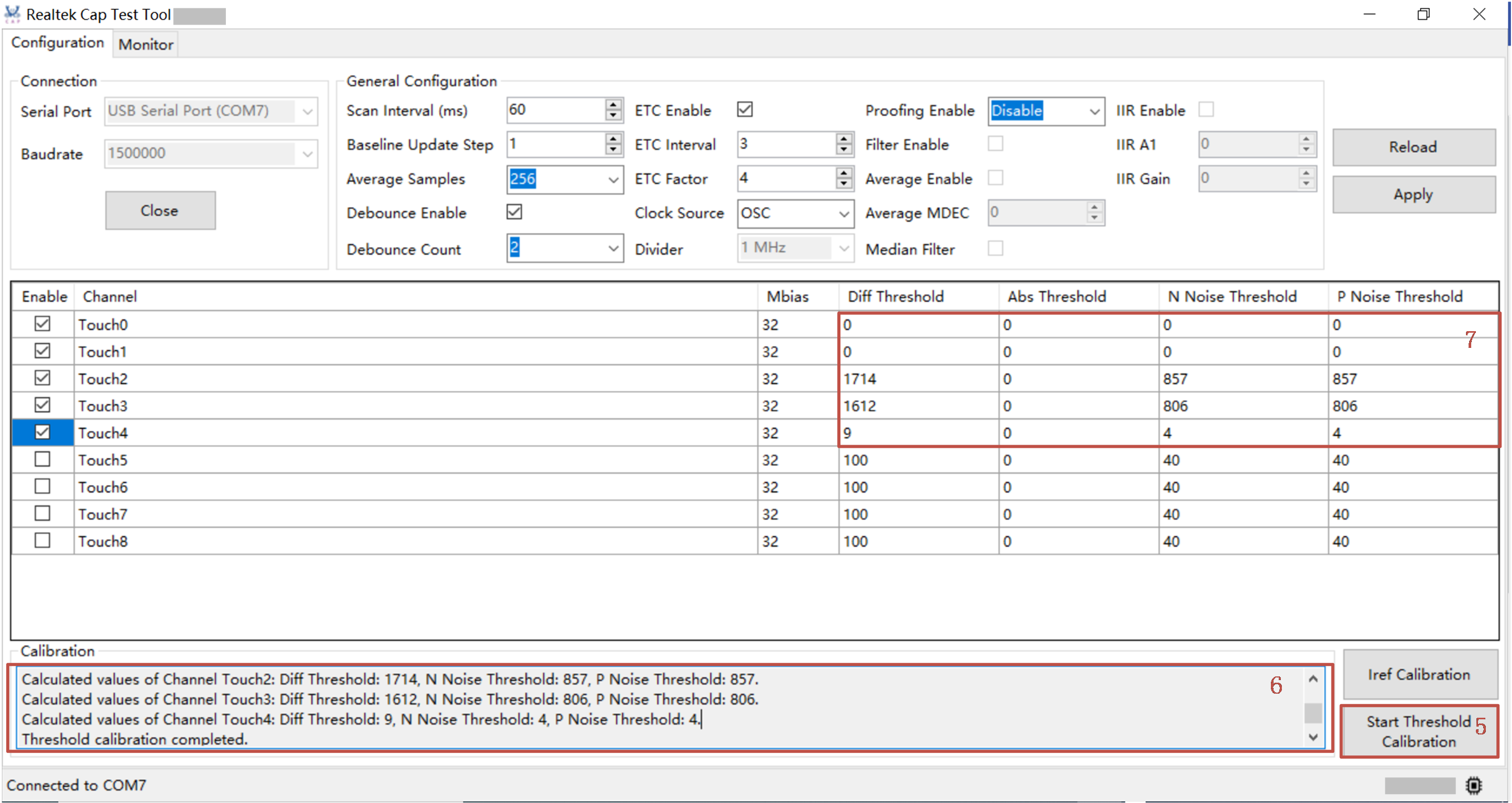
Threshold calibration operation (after calibration)
Note
Threshold calibration only works in ETC-enabled mode.
Diff threshold, N Noise threshold and P Noise threshold will be calculated and set to device based on the note in Step 6.
Abs Threshold is auto-set in device and won’t be updated after threshold calibration. Please click the
Reloadbutton if you want to load Abs Threshold value.
Caution
Remember to click the
Stop Threshold Calibrationbutton when completes, otherwise the threshold value won’t be calculated.
Monitor
Parameters
Parameter |
Value |
Comment |
|---|---|---|
Debug Enable |
0/1 |
Disabled now.
|
Debug Mode |
Manual/Auto |
Active when debug enabled. Debug mode usually works during debug/development process. |
Select View |
|
Different views of signals. |
Displayed Samples |
0~400 |
The sample number of raw data which is captured in active time. |
Sample Interval |
10~10000ms |
Sample interval in active time. |
Reset Baseline
Make sure the device is connected.
Go to the
Monitortab.Click the button.
Note
It will reset the baseline of all channels.
It has no association with the current monitor view.
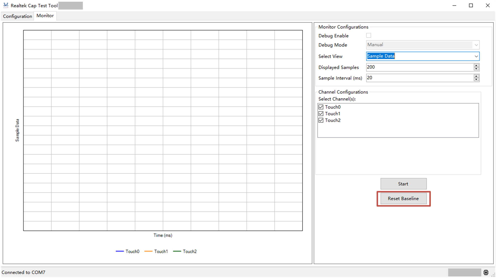
Reset baseline operation
Observe Signals
Make sure the device is connected.
Go to the :menuselection:` tab, and select the checkbox of channels which need to be enabled.
Go to the tab.
Change the
select Viewbox, and set the values ofDisplayed SamplesandSample Interval.Click the button and touch channels.
Click the button when completes.
Monitor boards of different views are shown in the following figures.
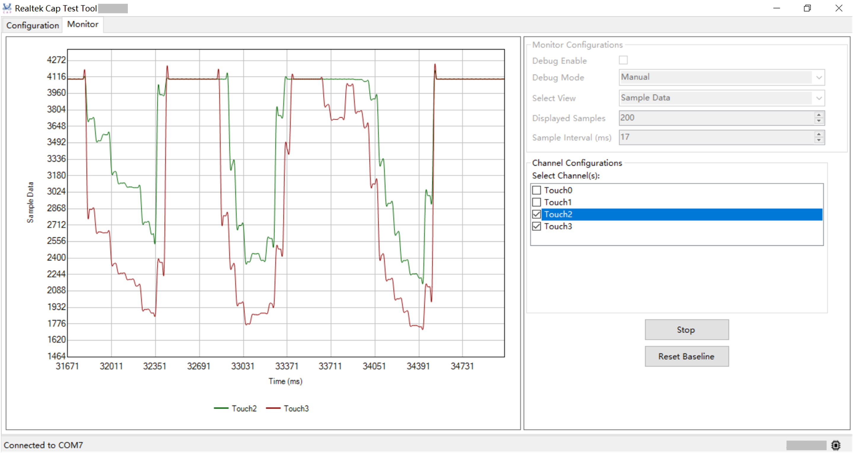
Monitor board (Sample Data View)
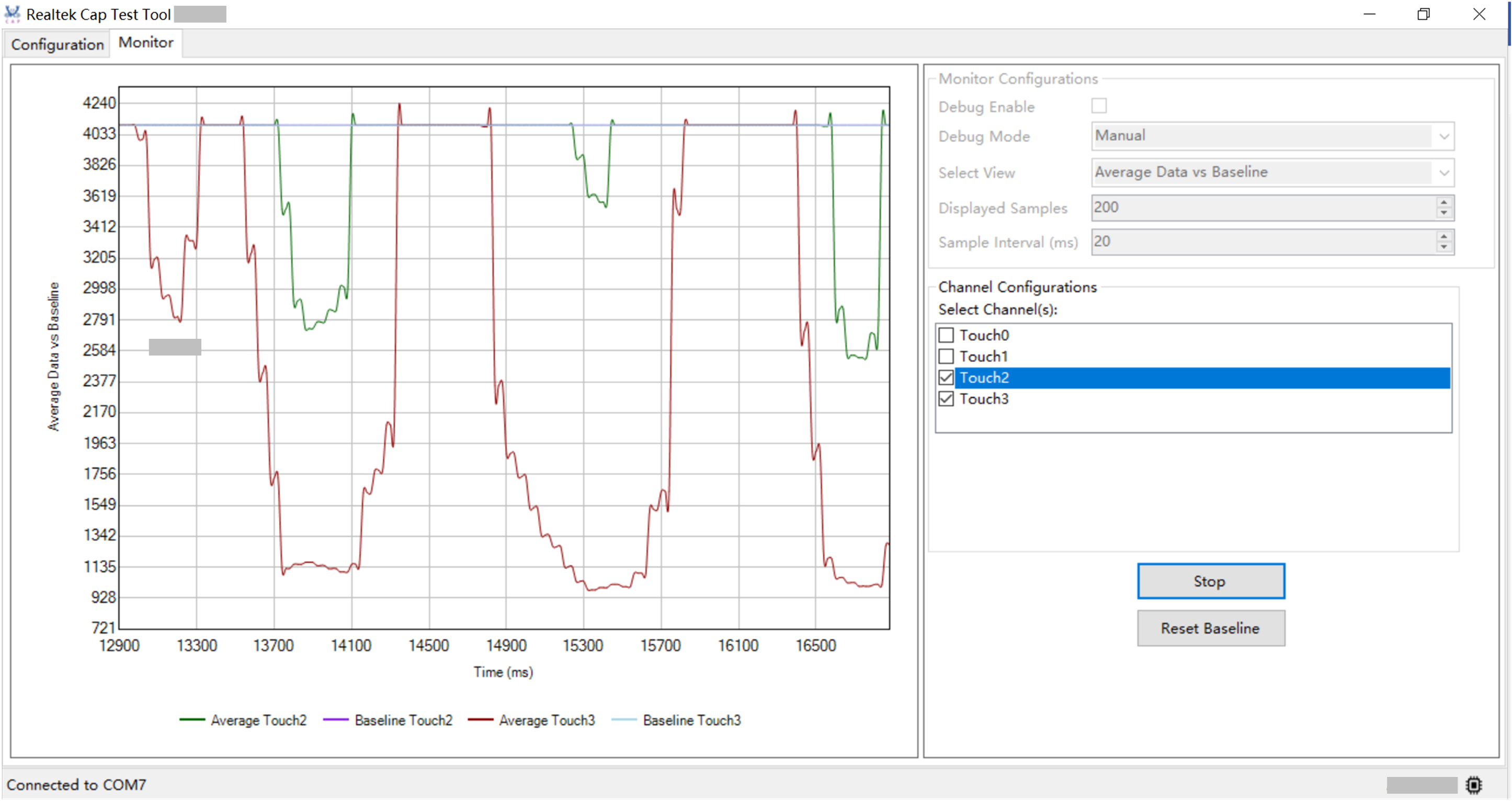
Monitor board (Average Data vs Baseline View)
Monitor board (Diff Data vs Diff Threshold View)
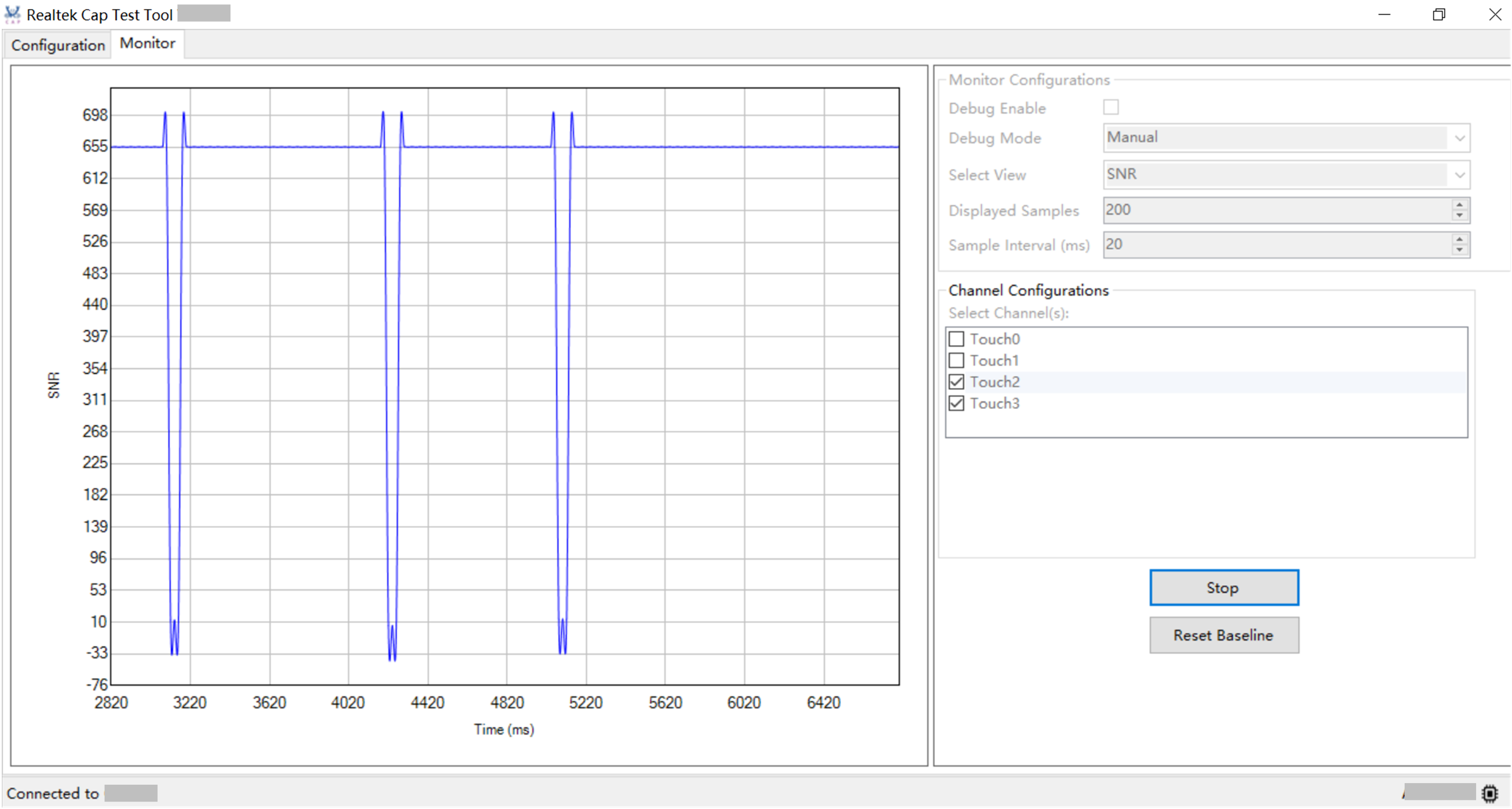
Monitor board (SNR View)
Note
In
Sample DataandAverage Data vs Baselineview,Select Channel(s)could be chosen before/in monitoring status.In
Diff Data vs Diff Thresholdview, the specific channel configuration could be customized by user before monitor starts.In
SNRview,Select Channel(s)is disabled since the signal-to-noise ratio is global data.