Supported ICs
Ameba SoC |
RTL8721Dx |
RTL8726EA |
RTL8720EA |
RTL8730E |
|---|---|---|---|---|
Supported |
Y |
N |
N |
N |
Wi-Fi R-Mesh Topology
As shown in the figure below, Wi-Fi R-Mesh is a tree-topology mesh network used to increase the Wi-Fi coverage, allowing stations that are far from the AP to also obtain a stable network connection.

Wi-Fi R-Mesh topology
Wi-Fi R-Mesh Advantage
The well-designed Wi-Fi R-Mesh has the following advantages:
A software-unsensible mesh network:
All Mesh protocols are implemented at Wi-Fi driver layer. Both root nodes and child nodes are regarded by the application as standard Wi-Fi stations connected to the AP.
No updates are required for Wi-Fi configuration programs.
Rapid pairing and switching within microseconds:
Child nodes can quickly switch to a new parent node with better signal quality without interrupting data communication.
If the parent node encounters a problem (such as power off or hang), the child node can rapidly detect the issue and switch to an alternative parent node without interrupting data communication.
A node can migrate all its child nodes to a new parent node while maintaining uninterrupted data flow.
High throughput across multiple hops:
R-Mesh forwarding bypasses the TCP/IP protocol stack, operating directly at the driver layer, utilizing less RAM and MCU resources.
With extremely short software processing time, better throughput can be achieved.
Network stability:
Simplified software architecture eliminates complex routing table algorithms, ensuring network stability.
Traditional mesh network issues like loops do not occur.
Wi-Fi R-Mesh Data Flow
Wi-Fi R-Mesh handles data forwarding directly at the Wi-Fi driver layer, requiring less RAM and MCU resources.
Due to the minimal software processing involved, nodes maintain good throughput even after several hops.

Wi-Fi R-Mesh data flow
Wi-Fi R-Mesh Capacity
The capacity of Wi-Fi R-Mesh refers to the maximum number of child nodes that can be connected to a root node.
The Wi-Fi R-Mesh topology diagram illustrates an example where the capacity is 4. Each root node can support up to 4 child nodes regardless of the topology.
Topology 0: All child nodes are directly connected to the root node.
Topology 3: The four nodes form a 4-hop linear network.
Can also be any other topologies between Topology 0 and Topology 3
Wi-Fi R-Mesh NAT (R-NAT)
In the R-Mesh network, each node establishes a real Wi-Fi connection with the AP. Consequently, the number of nodes that R-Mesh can support is constrained by the limited capacity of stations the AP can connect to.
To handle this limitation, we can implement a station + SoftAP solution based on the Network Address Translation (NAT) protocol to expand the number of nodes in R-Mesh. In this solution, the root node and its child nodes are connected to the SoftAP, rather than directly to the AP. The NAT protocol handles data forwarding between the AP network and the R-Mesh network.
In R-Mesh, such nodes are referred to as R-NAT nodes.
As illustrated in the figure below, the R-NAT node is positioned between the root node and the AP to extend the number of nodes that can access the network.

Wi-Fi R-NAT
Wi-Fi R-Mesh Throughput
Throughput
The throughput of Wi-Fi R-Mesh is listed in the following table:
Test scenario |
Layer |
UDP Tx (Mbps) |
UDP Rx (Mbps) |
TCP Tx (Mbps) |
TCP Rx (Mbps) |
|---|---|---|---|---|---|
Single Node |
Layer1 |
54.2 |
39.5 |
17.0 |
15.7 |
Layer2 |
19.6 |
18.8 |
9.6 |
10.0 |
|
Layer3 |
12.8 |
11.6 |
6.9 |
7.0 |
|
Layer4 |
9.4 |
8.2 |
5.4 |
5.2 |
|
Layer5 |
7.5 |
6.2 |
4.4 |
4.3 |
|
L1 + L2 |
Layer1 |
21.0 |
21.2 |
||
Layer2 |
12.5 |
14.0 |
|||
L1 + L2 + L3 |
Layer1 |
14.0 |
13.3 |
||
Layer2 |
7.0 |
7.2 |
|||
Layer3 |
5.1 |
6.4 |
|||
L1 + L2 + L3 + L4 |
Layer1 |
10.0 |
12.1 |
||
Layer2 |
4.0 |
8.4 |
|||
Layer3 |
3.6 |
6.7 |
|||
Layer4 |
3.0 |
4.0 |
|||
L1 + L2 + L3 + L4 + L5 |
Layer1 |
9.0 |
10.4 |
||
Layer2 |
3.2 |
3.7 |
|||
Layer3 |
2.5 |
2.9 |
|||
Layer4 |
2.3 |
1.8 |
|||
Layer5 |
1.8 |
2.1 |
Throughput Test
Similar to the regular Station or AP mode, we can test the throughput of R-Mesh via iperf command. As shown in the diagram below, simply input the iperf commands on the PC at the AP side and the node side.

R-Mesh throughput test
At R-Mesh node side, input the following AT command via UART:
AT+IPERF=-c,<server IP>,-i,<periodic>,-u,-b,<bandwidth>,-t,<transtime>,-p,<port>
At AP side (normally a PC), input the following iperf command via Terminal:
iperf -s -i <periodic> -u -p <port>
At R-Mesh node side, input the following AT command via UART:
AT+IPERF=-s,-i,<periodic>,-u,-p,<port>
At AP side (normally a PC), input the following iperf command via Terminal:
iperf -c <R-mesh node IP> -i <periodic> -u -b <bandwidth> -t <transtime> -p <port>
At R-Mesh node side, input the following AT command via UART:
AT+IPERF=-c,<server IP>,-i,<periodic>,-t,<transtime>,-p,<port>
At AP side (normally a PC), input the following iperf command via Terminal:
iperf -s -i <periodic> -p <port>
At R-Mesh node side, input the following AT command via UART:
AT+IPERF=-s,-i,<periodic>,-p,<port>
At AP side (normally a PC), input the following iperf command via Terminal:
iperf -c <R-mesh node IP> -i <periodic> -t <transtime> -p <port>
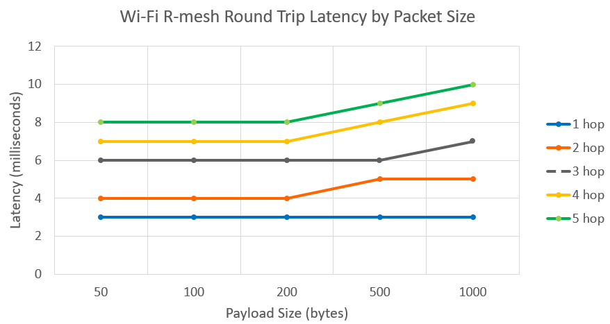
Wi-Fi R-Mesh RTT
Unlike BLE and ZigBee, R-Mesh has a very low Round-Trip Time (RTT) and and it does not significantly increase even as packet size increases.
Wi-Fi R-Mesh Demo Tool (Gravitation)
Test Environment
The AP and PC are connected via the network, and Gravitation is executed on the PC.

Test environment of Wi-Fi R-Mesh
Introduction
Gravitation can be used to visualize all R-Mesh nodes connected to the AP and their topology, with the following key features:
Real-Time network topology monitoring and dynamic updates
Integrated ping test
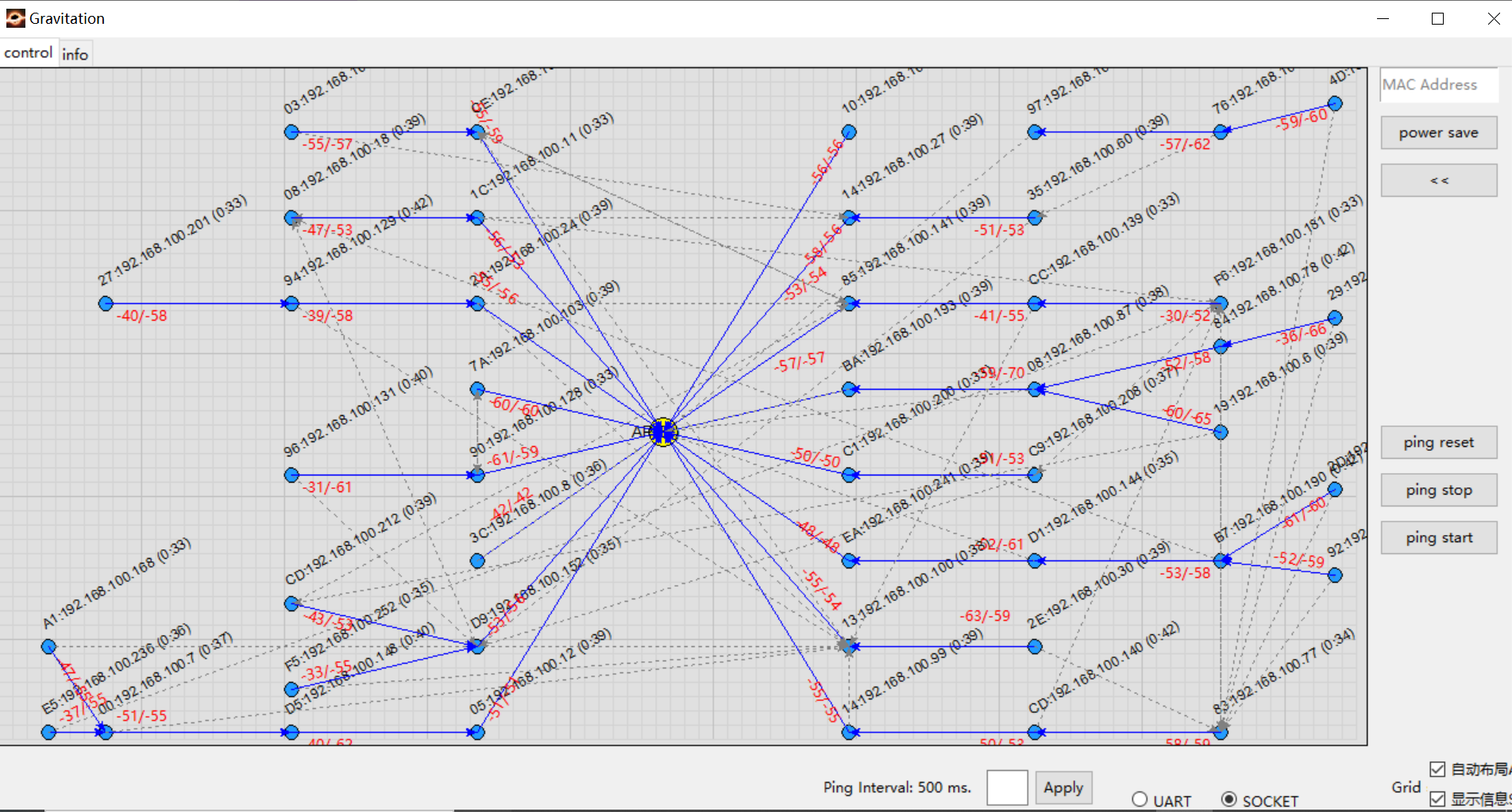
Gravitation UI
Each node will display MAC_Addr:IP(update time). For example: CE:192.168.1.100(5:6) indicates that the MAC address is XX:XX:XX:XX:0xCE, and the IP address is 192.168.1.100. The two red numbers displayed on the connection line between nodes represent the current parent node’s score and the optimal candidate node’s score, which are calculated based on signal strength.
Gravitation and R-Mesh nodes communicate via socket connections. Nodes periodically send their IP addresses, parent node MAC addresses, and other information to the PC running Gravitation through sockets. Gravitation parses this data and displays the real-time topology.
Users can reference this design to redevelop their own applications for capturing and visualizing the topology of R-Mesh networks.
Usage
Gravitation is located at {sdk}/tools/R-Mesh_Demo_Tool.
The test step is as follows:
Connect AP and PC via network, and execute
gravitation.exe.Open the file
config.yamlin the gravitation folder and config the AP(s) to be tested (several APs can be added simultaneously).ap_mac_list: - 00:11:22:33:44:55
Configure the ping interval and packet size (default parameters will be used if not configured).
ping:
interval: 500
packet_size: 64
The ping interval can also be directly configured via the Gravitation UI.
After these steps, Gravitation configuration is complete. Close Gravitation and relaunch
gravitation.exeto apply all configurations immediately.Use the AT command to connect each test node to the AP. Nodes will automatically form a Mesh network afterward. The connection status of each node and network topology can be observed in Gravitation.
AT+WLCONN=ssid,rmesh_test,pw,12345678
To manually drag nodes for layout customization, uncheck the
Auto Layoutoption at the bottom-right of the UI. By default, Gravitation uses automatic layout, allowing AP dragging but restricting R-Mesh node movement.Gravitation employs automatic information display by default, showing partial node information for each node automatically shown in the top-right of the node. You can disable this automatic display by unchecking the
Show Informationoption at the bottom-right of the UI.In manual mode, clicking a node will display its full MAC/IP address in the top-right corner, along with a scan list containing details of nearby nodes (e.g., last byte of MAC address, signal strength).
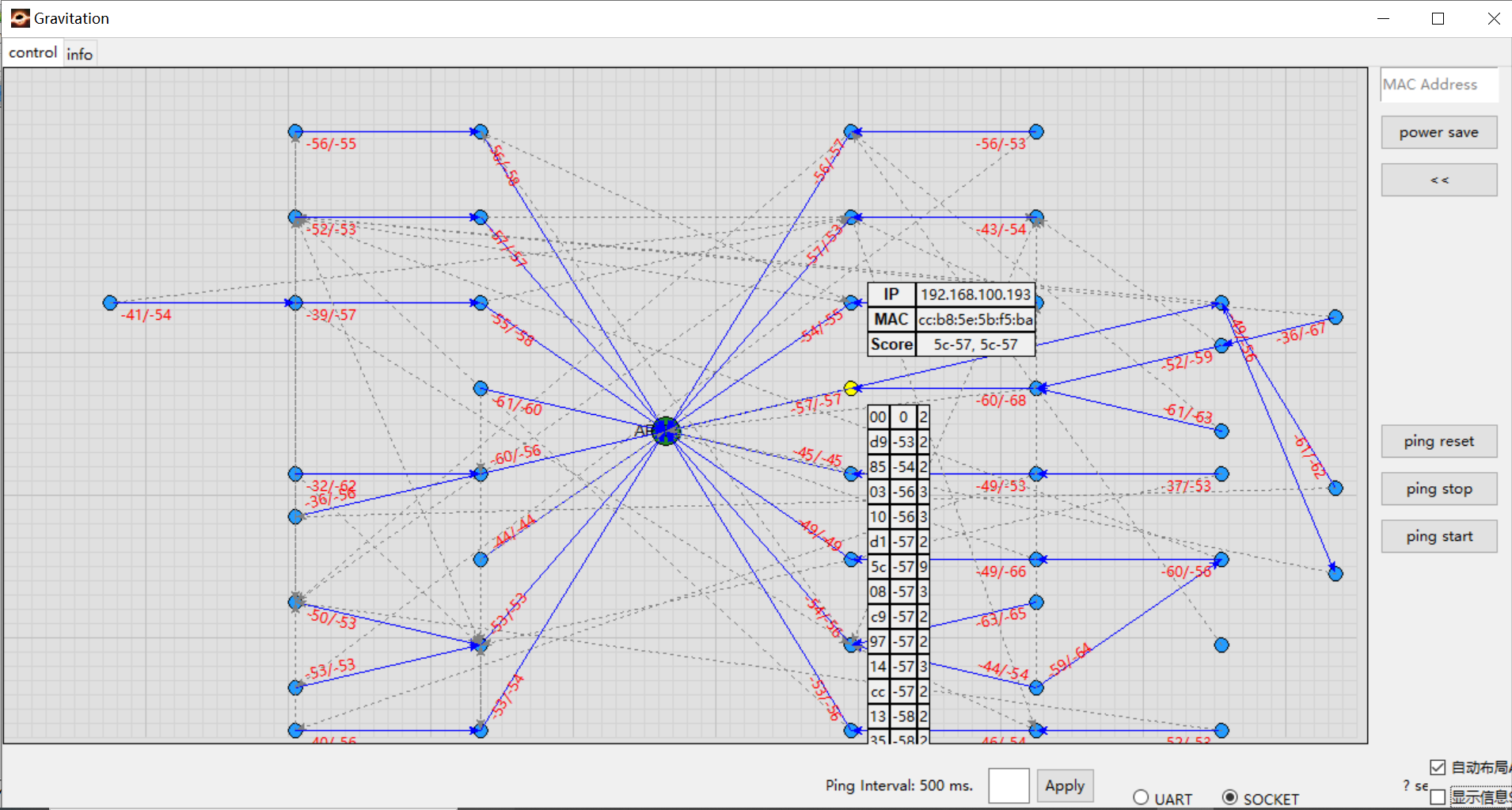
Display information manually
Wi-Fi R-Mesh Parameter Configuration
Only a limited number of parameters needs to be configured before using R-Mesh (default parameters will be used if not configured).
Open {sdk}/component/soc/usrcfg/amebadplus/ameba_wificfg.c, and modify the following parameters accordingly, then recompile the SDK to apply.
/*R-Mesh*/
wifi_user_config.wtn_en = 0;
wifi_user_config.wtn_strong_rssi_thresh = -50;
wifi_user_config.wtn_father_refresh_timeout = 3000;
wifi_user_config.wtn_child_refresh_timeout = 4000;
...
wifi_user_config.wtn_max_node_num = 15;
...
Where
- wifi_user_config.wtn_en:
The main switch of R-Mesh function, setting to 1 will enable R-Mesh function. All R-Mesh nodes and R-NAT nodes must set this parameter to 1.
- wifi_user_config.wtn_strong_rssi_thresh:
When RSSI is above this threshold, the node will act as a root node or a R-NAT node, connecting directly to the AP.
- wifi_user_config.wtn_father_refresh_timeout:
Unit is milliseconds. If the node does not receive a beacon from father node within this time, it will try to switch to a new father node.
- wifi_user_config.wtn_child_refresh_timeout:
Unit is milliseconds. If the node does not receive a beacon from child node within this time, it will delete this child node.
- wifi_user_config.wtn_max_node_num:
The maximum number of nodes in R-Mesh network, used to determine the beacon window size for each node. The more nodes there are, the smaller the beacon window and the longer beacon interval will be.
Wi-Fi R-Mesh NAT Parameter Configuration
The R-Mesh NAT function is disabled by default. Please follow the steps below to configure it, then refer to Wi-Fi R-Mesh SDK Obtain and Compile for compilation.
Open
{sdk}/component/soc/usrcfg/amebadplus/ameba_wificfg.c, and modify the following parameters accordingly./*R-Mesh*/ ... wifi_user_config.wtn_rnat_en = 0; wifi_user_config.wtn_fixed_rnat_node = 0; wifi_user_config.wtn_connect_only_to_rnat = 0; ...
Where
- wifi_user_config.wtn_rnat_en:
The main switch of R-Mesh NAT function, setting it to 1 will enable R-Mesh NAT function. Enabled when the device needs to become an R-NAT node, otherwise disabled.
- wifi_user_config.wtn_fixed_rnat_node:
Controls whether to force becoming an R-NAT node (only takes effect when when
wifi_user_config).wtn_rnat_en=1.Setting to 1: Force the device to act as an R-NAT node
Setting to 0: Whether the device becomes an R-NAT node depends on the signal strength with the AP
- wifi_user_config.wtn_connect_only_to_rnat:
Controls whether the device can only connect to R-NAT nodes.
- wifi_user_config.ap_sta_num:
For R-NAT node, represents the maximum number of clients that can directly connected.
When the number is configured to be more than 5, it is necessary to modify the memory layout.
Current maximum support: 14 clients.
When
wifi_user_config.ap_sta_numis modified, if you need to adjust the memory layout, open the file{sdk}/amebadplus_gcc_project/amebaDplus_layout.ld, and modify the value ofRAM_KM0_IMG2_SIZEfrom the default 96K to 116K to enable R-NAT nodes to directly support connections with up to 14 clients.#define RAM_KM0_IMG2_SIZE KBYTES(116)Modify menuconfig to enable the NAT feature of LWIP, as the R-Mesh NAT function requires it.
Execute
./menuconfig.pyunder{sdk}/amebadplus_gcc_project, and select .----Connectivity config---- CONFIG WHC INTF ---> ... CONFIG LWIP ---> [ ] Enable Fast DHCP [*] Enable NAT REPEATER [*] Enable LWIP NETCONN SEM PER THREAD [ ] Enable LWIP Debug ...
Wi-Fi R-Mesh SDK Obtain and Compile
Obtain SDK and R-Mesh WLAN libraries:
By default, the root node’s R-Mesh capacity is only 2. If you need the R-Mesh capacity to be 4 nodes, obtain an additional R-Mesh WLAN library via <claire_wang@realsil.com.cn>.
Download SDK: IoT SDK
Compile the default R-Mesh SDK
Set
wifi_user_config.wtn_en=1, and configure other R-Mesh related parameters in wifi_user_config according to your requirements.Build the image to test R-Mesh.
If you need to test the scenario which R-Mesh capacity is 4 nodes, follow these steps after obtaining the additional R-Mesh WLAN libraries:
Replace
lib_wifi_whc_ap.ain{sdk}/amebadplus_gcc_project/project_km4/asdk/lib/application.Replace
lib_wifi_common.a,lib_wifi_fw.aandlib_wifi_whc_np.ain{sdk}/amebadplus_gcc_project/project_km0/asdk/lib/application.Build the image to test R-Mesh.
R-Mesh Memory Size
Enabling R-Mesh will consume additional memory of the following size:
Item |
KM0 |
|---|---|
txt |
22KB |
rodata |
2.4KB |
data+bss |
0.9KB |
heap |
20KB |