Introduction
The OTA (Over-The-Air) update mechanism allows devices to self-update based on received data through WiFi, SPI, UART, or file systems while image is running normally, enabling timely upgrades to device functionality and performance.
Before using OTA, please refer to the Flash Layout section for details about Flash layout.
Image Slot
Two image slots (OTA1 and OTA2) are configured in Flash layout for redundant storage and version control. The positions of OTA1 and OTA2 in the Flash layout can be found in Flash Layout. The boot system selects between these slots based on validation criteria.
Image Pattern and Version Number
Boot selection between OTA1/OTA2 primarily depends on the image pattern and version number in Certificate and Manifest. As shown below, both the Certificate and Manifest contain an 8-byte image pattern, a 2-byte major version number, and a 2-byte minor version number..

The image pattern is data with a fixed length of 8 bytes. The OTA selection process checks the validity of the image pattern. The bootloader and application have different image pattern, with the bootloader checking the image pattern in the Manifest, and the application checking the image pattern in the Certificate.
The version number is a 4-byte combination of the major version and the minor version. The version number is calculated as follows:
The OTA selection process compares the size of the version numbers. The bootloader and application can have different version numbers, with the bootloader checking the version number in the Manifest, and the application checking the version number in the Certificate.
On the next boot after an OTA upgrade, the bootloader checks the validity of the image pattern and compares the version numbers to decide whether to boot from OTA1 or OTA2. Consistency between image pattern and versions ensures reliable boot. Each image must check the following items:
Check the validity of the image pattern for both OTA1 and OTA2.
If only one image pattern is valid, boot from the valid image.
If both image patterns are invalid, boot fail.
Compare the version number of OTA1 and OTA2.
If both OTA1 and OTA2 are valid and with different version numbers, the device will boot from the image with a bigger version.
If both OTA1 and OTA2 are valid but with the same version number, the device will boot from OTA1.

OTA selection diagram
To switch to the new image on the next boot after an upgrade, OTA supports the following two methods:
Set a higher version number in the new image’s Manifest. The next boot will use the new image. This requires modifying the new image’s version number during each upgrade.
Modify the version number in the project’s manifest.json file:
Configure the version number for the bootloader. The version number range is from 0 to 32767:
"boot":
{
   "IMG_ID": "0",
   "IMG_VER_MAJOR": 1,
   "IMG_VER_MINOR": 1,
   ...
},
Configure the version number for the application. The version number range is from 0 to 65535:
"app":
{
   "IMG_ID": "1",
   "IMG_VER_MAJOR": 1,
   "IMG_VER_MINOR": 1,
   ...
},
Invalidate the old image’s image pattern. After the update, overwrite the old image’s image pattern (e.g., set all bytes to 0) to mark it as invalid. The next boot will then use the new image without modifying the version number.
Enable this method by setting OTA_CLEAR_PATTERN to 1 in ameba_ota.h.
Users can choose either Depends on Version Number or Depends on Version Number depending on their needs.
Anti-rollback
Anti-rollback is the function to prevent version rollback attacks. When the anti-rollback is enabled, the version number in the certificate or manifest cannot be less than the anti-rollback version set in OTP. Otherwise, this image will be regarded as invalid and the chip will not boot from this invalid image.
Typically, if OTA update is security-related, users can program a higher anti-rollback version number in OTP and simultaneously update image with a major version greater than the anti-rollback version number to prevent rollback attacks.
The anti-rollback process is as follows:
The device individually compares the major version numbers abtained from OTA1 and OTA2 images with the anti-rollback version number in OTP.
If the image’s major version number is less than the anti-rollback version number, this image will be regarded as invalid.

Users can enable the anti-rollback feature through the following steps:
Change the anti-rollback version number for the bootloader. By default, all images use the same anti-rollback version in the OTP as a threshold to prevent rollback attacks.
Name
OTP Address
Length
Description
Bootloader Version
Physical Address 0x36E~0x36F
16 bits
Anti-rollback version for the bootloader
The default value for the bootloader’s anti-rollback version is 0. Users can alter the number of 0 bits to increase the bootloader version.
For example, to set the bootloader anti-rollback version to 1, use the following command:
EFUSE wraw 36E 2 FFFE
Write into the OTP to enable anti-rollback with the following command:
EFUSE wraw 368 1 BF
Note
Once anti-rollback is enabled, it cannot be disabled.
If the bootloader and application do not use the same anti-rollback version, modify
BOOT_OTA_GetCertRollbackVer()in bootloaderboot_ota_km4.c or bootloaderboot_ota_hp.c and define another anti-rollback version for the application in the OTP.
Bootloader
OTA Image
The KM4 bootloader image (km4_boot_all.bin) can be updated via OTA and is capable of booting from either OTA1 or OTA2.
The layout of KM4 bootloader image is illustrated below.

To enable bootloader upgrade via OTA, follow these steps:
Enter
CONFIG OTA OPTIONvia Configuring SDK (menuconfig), and selectEnable Bootloader OTA, integrating the bootloader image into ota_all.bin.Write the bootloader’s OTA2 address into the OTP. Use the IMG_BOOT_OTA2 setting in Flash_Layout as a reference, as explained in User Configuration.
EFUSE wraw 36C 2 IMG_BOOT_OTA2
For example, if IMG_BOOT_OTA2 is 0x08200000, the command to write into the OTP would be:
EFUSE wraw 36C 2 0082
Note
The bootloader OTA2 address is the value in OTP address 0x36C shifted left by 12 bits, or the value at OTP address 0x36C multiplied by 4K.
If the default address for bootloader OTA2 is 0xFFFFFFFF, the bootloader will not be upgraded during OTA, and the device will always boot from bootloader OTA1.
OTA Selection Flow
The ROM bootloader selects OTA image based on the version number in the KM4 bootloader’s Manifest.

Application
OTA Image
The application image (km0_km4_app.bin) comprises KM0, KM4 non-secure and KM4 secure application images.
This image can be updated via OTA and is capable of booting from either OTA1 or OTA2. The layout of the application image is illustrated below.

The application image (kr4_km4_app.bin) comprises KR4, KM4 non-secure and secure application images.
This image can be updated via OTA and is capable of booting from either OTA1 or OTA2. The layout of the application image is illustrated below.
There are two schemes to load DSP image. Refer to DSP Image for details.
DSP Image
There are two schemes for users to load the DSP image.
We choose the scheme of DSP Image within Application Image and use kr4_km4_dsp_app.bin in the following operations.
In this scheme, there are two slots in Flash layout called IMG_APP_OTA1 and IMG_APP_OTA2 respectively.
Since the DSP image is merged into the application image. In order to avoid issues such as DSP boot fail after the DSP image
is updated through OTA application when there is only one slot for DSP. For MP devices,
the scheme of the DSP image within application image is recommended, which DSP can choose to boot from OTA1 or OTA2.
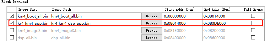
After choosing this scheme, there is only one application image called kr4_km4_dsp_app.bin needed to be downloaded as shown below.
Steps of generating kr4_km4_dsp_app.bin are:
Navigate to project and open configuration menu.
Select to enable the configuration of
DSP within APP image.Select to set path of
dsp.bin, click Enter to save.*** --------MENUCONFIG FOR General--------- *** CONFIG DSP Enable ---> [*] Enable DSP [*] DSP within APP image (../component/dsp) DSP_IMAGE_TARGET_DIR CONFIG TrustZone ---> ...
Note
The DSP_IMAGE_TARGET_DIR is relative to the amebalite_gcc_project.
Save and exit.
For example, once the DSP SDK compilation is completed, two images will be generated: dsp.bin and dsp_all.bin,
which are located in the {DSP_SDK}\project\image directory.
Copy the
dsp.bininto{SDK}\component\dsp, so the path ofdsp.binis../component/dsp.Set the path as described in Step 3 above. Check the path in
SDK\amebalite_gcc_project\menuconfig\.config.# CONFIG DSP Enable # CONFIG_DSP_EN=y CONFIG_DSP_WITHIN_APP_IMG=y CONFIG_DSP_IMAGE_TARGET_DIR="../component/dsp" # end of CONFIG DSP Enable
Rebuild the project using the following commands. The
kr4_km4_dsp_app.bincan be found in{SDK}\amebalite_gcc_project.cd amebalite_gcc_project ./build.py
In this scheme, there is only one slot in Flash layout called IMG_DSP for the DSP image.
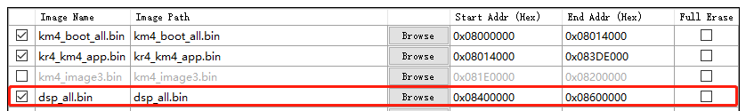
When the DSP application is modified, users only need to re-download the DSP image called dsp_all.bin to IMG_DSP as shown below.
So when in device DSP-development stage, we recommend this method to develop the DSP application conveniently and efficiently.
To choose this scheme, users can disable the configuration of DSP within APP image by the following steps:
Navigate to project and open configuration menu.
cd amebalite_gcc_project
./menuconfig.py
Remove the selection .
*** --------MENUCONFIG FOR General--------- ***
CONFIG DSP Enable --->
   [*] Enable DSP
   [ ] DSP within APP image
CONFIG TrustZone  --->
...
Save and exit.
Note
This scheme should be used only in device DSP-development stage.
The application image (kr4_km4_app.bin) comprises KR4, KM4 non-secure and secure application images.
This image can be updated via OTA and is capable of booting from either OTA1 or OTA2. The layout of the application image is illustrated below.
The application image (km0_km4_ca32_app.bin) comprises KM0, KM4 non-secure, KM4 secure and CA32 application images.
This image can be updated via OTA and is capable of booting from either OTA1 or OTA2. The layout of the application image is illustrated below.
OTA Selection Flow
The KM4 bootloader selects application image based on the version number in the application’s Certificate, as depicted below.

OTA Compressed Image
When the OTA Image Compression is enabled, the application image will be compressed and image size will be reduced, which can save the flash space effectively.
The OTA Image Compression only compresses the application image which named with suffix of app.bin. After compression finishes, the compressed application image will be generated in directory image with suffix app_compress.bin. Additionally, the compressed application image will be integrated into ota_all.bin, which will be used in OTA applications.
The compression algorithm uses LZMA. LZMA stands for Lempel-Ziv-Markov chain Algorithm. It is a lossless data compression algorithm developed by Igor Pavlov, known for its high compression ratio and relatively low decompression memory requirements. The LZMA algorithm is commonly used in 7z format compressed files and is widely applied in 7-Zip software.
Here, we use compression rate to represent compression efficiency. The compression rate is calculated as follows:
The compression rate can be influenced by the content of the image. Usually, the compression rate is in the range of 50 to 70 percent. The more complex of the original image content, the higher compression rate will be.
The boot process after enabling the OTA compression feature has the following characteristics:
If the compressed image’s version number is equal to or greater than the non-compressed image’s version number, the system selects the compressed image.
The compressed image is decompressed, overwriting the old image in the other slot.
Once decompression is successful, the compressed image’s image pattern is cleared.
The compressed image is decompressed only once during the first boot after download and won’t be decompressed again after that.

When enabling the OTA compression feature, we recommend storing the non-compressed image in the OTA1 and the compressed image in the OTA2. Users can plan the Flash layout in advance based on the compression rate.
An example is provided as shown in the following figure:
The device starts and runs the OTA application from OTA1.
The compressed image is downloaded into OTA2.
On the next boot, the system will select the compressed image, decompress it to OTA1, and then continue booting from OTA1.

Users can generate OTA compressed image by the following steps:
Enter
CONFIG OTA OPTIONvia Configuring SDK (menuconfig), and checkEnable Compress APP Imageto enable OTA compression feature.Build the project, and the
ota_all.bincontaining the compressed application image will be generated in {SDK}amebaxxx_gcc_project.
Building OTA Image
Modifying Configurations
Select the method for booting new image as discussed in Image Pattern and Version Number.
Adjust the bootloader’s anti-rollback version number and enable anti-rollback if necessary, as outlined in Anti-Rollback.
If upgrading the bootloader is needed, follow the steps outlined in Bootloader.
If OTA compression is needed, follow the steps outlined in OTA Compressed Image.
Generating OTA Image Automatically
The OTA image will be generated automatically when building the project.
The application image
xxx_app.binis comprised inota_all.binby default.Build the project. The OTA image file (
ota_all.bin) will be generated in{SDK}\amebaxxx_gcc_project.
OTA Image Format
The ota_all.bin format is illustrated below.

Items |
Address offset |
Size |
Description |
|---|---|---|---|
Version |
0x00 |
4 bytes |
Version of OTA File Header, default is 0xFFFFFFFF. |
Header Number |
0x04 |
4 bytes |
Number of OTA File Header. Value can be 1, 2. |
Signature |
0x08 |
4 bytes |
OTA File Header’s signature is string. Value is |
Header Length |
0x0C |
4 bytes |
Length of OTA File Header. Value is 0x18 * Header Number. |
Checksum |
0x10 |
4 bytes |
Checksum of upgrade image. |
Image Length |
0x14 |
4 bytes |
Size of upgrade image. |
Offset |
0x18 |
4 bytes |
Start position of upgrade image in current image. |
Image ID |
0x1C |
4 bytes |
Image ID of upgrade image:
|
Updating via Wireless Network
This section introduces the design principles and usage of OTA via wireless network server. It has well-transportability to porting to users’ OTA applications which is upgraded from users’ server.
The OTA from network server shows how the device upgrades the image from a network download server. The network download server sends the image to the device based on the network socket, as the following figure illustrates.

Note
Make sure both the device and the PC are connecting to the same local network.
OTA Example
Follow these steps to run the OTA example to upgrade from HTTP server:
If
Depends on Image Patternwas chosen in Modifying Configurations, make the modifications describedDepends on Image Pattern, otherwise skip this step.Edit example_ota.c.
Edit the host according to the server IP address.
#define PORT   8082
static const char *host = "192.168.31.193";   //"m-apps.oss-cn-shenzhen.aliyuncs.com"
static const char *resource = "ota_all.bin"; //"051103061600.bin"
Edit the OTA type to
OTA_HTTP.ret = ota_update_init(ctx, (char *)host, PORT, (char *)resource, OTA_HTTP);
Rebuild the project with the command
./build.py -a otaand download the images to the device.If
Depends on Version Numberwas chosen in Modifying Configurations, make the modifications described inDepends on Version Number, otherwise skip this step.Rebuild the project with the command
./build.pyand copyota_all.bininto DownloadServer(HTTP).Edit http_server.py.
server_ip = '192.168.31.193'
server_port = 8082
Execute the script by command
python http_server.pyto start the download server program.Reset the device and connect to the HTTP server.
After image download is complete, the device will reset automatically and boot from the new image .
User Configuration
Refer to the section Flash Layout for Flash layout. Modify the Flash layout if necessary, users should plan the Flash layout in advance and allocate sufficient space.