Introduction
The Global Direct Memory Access (GDMA) controller, also referred to as DMAC, is primarily designed for transferring data between memory and peripherals via the AXI/OCP bus without CPU intervention, thereby offloading computational overhead from the CPU.
The GDMA controller comprises 8 channels:
Channel 0 and Channel 1 have a 128-byte FIFO buffer.
Other channels have a 32-byte FIFO buffer.
Featuring a dual AXI/OCP master bus architecture, the GDMA incorporates a slave interface for configuration and programming. It supports hardware-based priority arbitration and programmable priority between DMA requests.
DMAC Performance
The data-transmission efficiency of GDMA is affected by clock synchronization, channel FIFO depth, transfer types, handshake efficiency, GDMA interface setting of slave and other factors. The following data is based on the results of the experiment with the transmission type of single block and the transmission channel is zero.
The data transmission efficiency of the GDMA is influenced by clock synchronization, channel FIFO depth, transfer type, handshake efficiency, GDMA slave interface configurations, and other factors. The experimental data below is derived from tests conducted under single-block transfer mode with channel 0.
Slave |
Clock (Hz) |
Writing 64 bytes |
Reading 64 bytes |
|---|---|---|---|
SRAM |
250M |
(64*8)/(280ns)= 1828.57Mbps |
(64*8)/(240ns)= 2133.33Mbps |
PSRAM |
250M |
(64*8)/(350ns)= 1462.86Mbps |
(64*8)/(360ns)= 1422.22Mbps |
Audio |
40M |
(64*8)/(1050ns)= 487.62Mbps |
(64*8)/(470ns)=1089.36Mbps |
SPI |
100M |
(64*8)/(710ns)= 721.13Mbps |
(64*8)/(670ns)= 764.18Mbps |
Slave |
Clock (Hz) |
Writing 64 bytes |
Reading 64 bytes |
|---|---|---|---|
SRAM |
300M |
(64*8)/(500ns)=1024Mbps |
(64*8)/(340ns)=1505.88Mbps |
PSRAM |
250M |
(64*8)/(270ns)=1896.30Mbps |
(64*8)/(400ns)=1280Mbps |
DDR |
530M |
(64*8)/(250ns)=2048Mbps |
(64*8)/(310ns)=1651.61Mbps |
Audio |
40M |
(64*8)/(1200ns)=426.67Mbps |
(64*8)/(410ns)=1248.78Mbps |
SPI |
75M |
(64*8)/(510ns)=1003.92Mbps |
(64*8)/(700ns)=731.43Mbps |
Note
The time of GDMA turn-around is not included.
DMAC Configuration
The diagram of DMA block size is figured below:

Data Size
The figure above illustrates the setting of GDMA transmission data size. The block_ts indicates the amount of data that will be transferred in a single data block. It needs to be set to the total number of data/SRC_TR_WIDTH, and the maximum value is 0xFFFF.
Transfer Direction and Flow Controller
There are currently four transmission directions and two flow controller settings, with a total of eight available configurations.
When the peripheral acts as a flow controller, the DMA transfers data according to the single/burst requests issued by the peripheral.
When the DMAC acts as a flow controller, all requests from the peripheral will be processed according to the configured requests.
TT_FC[2:0] field of CTLx register (x is channel) |
Direction |
Flow controller |
|---|---|---|
000 |
Memory to Memory |
DMAC |
001 |
Memory to Peripheral |
DMAC |
010 |
Peripheral to Memory |
DMAC |
011 |
Peripheral to Peripheral |
DMAC |
100 |
Peripheral to Memory |
Peripheral |
101 |
Peripheral to Peripheral |
Source Peripheral |
110 |
Memory to Peripheral |
Peripheral |
111 |
Peripheral to Peripheral |
Destination Peripheral |
Note
The block_ts parameter can only be set when the DMAC is used as a flow controller.
Transfer msize
The length of each transaction can be configured.
msize > 1: burst transaction
msize = 1: single transaction
SRC_MSIZE[2:0]/DEST_MSIZE[2:0] field of CTLx register |
Transfer msize |
|---|---|
000 |
1 |
001 |
4 |
010 |
8 |
011 |
16 |
100 and above |
Not supported |
Transfer Width
The GDMA supports the following transmission width.
SRC_TR_WIDTH[2:0]/DST_TR_WIDTH[2:0] field of CTLx register |
Transfer width (byte) |
|---|---|
000 |
1 |
001 |
2 |
010 |
4 |
011 and above |
Not supported |
Note
When reading and writing peripherals, the SRC_TR_WIDTH/DST_TR_WIDTH is completely determined by the width of peripherals.
When reading and writing memory:
If cache is disabled, the address does not need to be aligned to any value. It only needs to be SRC_TR_WIDTH divisible by the total amount of data so that the block_ts is an integer.
If cache is enabled, buffer boundary addresses and cache line alignment are necessary.
If memory is destination (P2M, M2M), DST_TR_WIDTH parameter will be ignored, and writing are always based on the bus width (typically 32 bits, 4 bytes).
Transfer Types
Single Block
Single block DMA transfer – Consists of a single block.
Multi-block
Multi-block DMA transfer – DMA transfer may consist of multiple RTK_DMAC blocks. Multi-block transfer types include:
Auto-reloading mode
Linked list mode
Auto-reloading Mode
In auto-reloading mode, the source and destination can independently select which method to use.
Auto-reloading transfer types |
Setting |
Introduction |
|---|---|---|
Src auto reload |
PGDMA_InitTypeDef->GDMA_ReloadSrc = 1 PGDMA_InitTypeDef->GDMA_ReloadDst = 0 |
For multi-block transfers, the SAR register can be auto-reloaded from the initial value at the end of each block, and DST address is contiguous, as shown in Multi-block DMA transfer with source address auto-reloaded and contiguous destination address. |
Dst auto reload |
PGDMA_InitTypeDef->GDMA_ReloadSrc = 0 PGDMA_InitTypeDef->GDMA_ReloadDst = 1 |
For multi-block transfers, the DAR register can be auto-reloaded from its initial value at the end of each block, and the SRC address is contiguous. |
Src & Dst auto reload |
PGDMA_InitTypeDef->GDMA_ReloadSrc = 1 PGDMA_InitTypeDef->GDMA_ReloadDst = 1 |
For multi-block transfers, the SAR and DAR register can be auto-reloaded from its initial value at the end of each block, as shown in Multi-block DMA transfer with source and destination address auto-reloaded. |
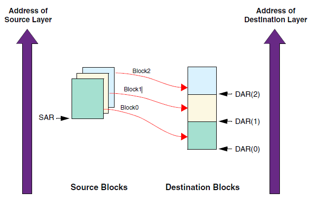
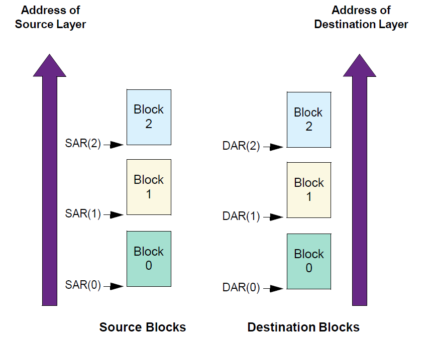
Multi-block DMA transfer with source address auto-reloaded and contiguous destination address
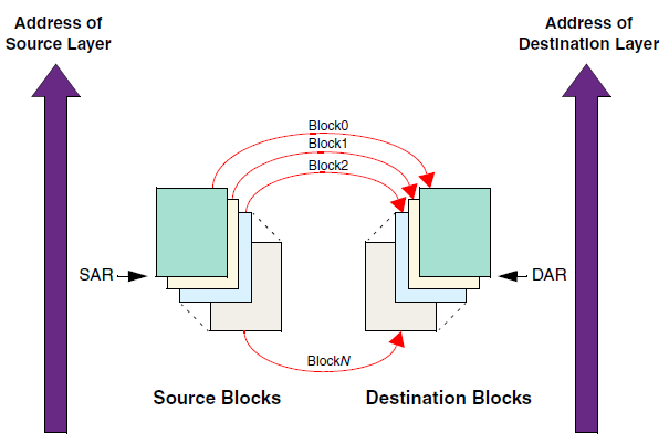
Multi-block DMA transfer with source and destination address auto-reloaded
Linked list Mode
In linked list mode, the addresses between data blocks do not have to be consecutive.
Link list transfer types |
Setting |
Introduction |
|---|---|---|
Src: Continue address Dst: Link list |
PGDMA_InitTypeDef->GDMA_SrcAddr = pSrc PGDMA_InitTypeDef->GDMA_LlpDstEn = 1 |
Source memory is a continuous data block, while destination data blocks are organized in linked list. |
Src: Auto-reloading Dst: Link list |
PGDMA_InitTypeDef->GDMA_ReloadSrc = 1 PGDMA_InitTypeDef->GDMA_SrcAddr = pSrc PGDMA_InitTypeDef->GDMA_LlpDstEn = 1 |
In source, SAR register can be auto-reloaded from the initial value at the end of each block, as shown in Multi-block DMA transfer with source address auto-reloaded and linked list destination address. |
Src: Link list Dst: Continue address |
PGDMA_InitTypeDef->GDMA_LlpSrcEn = 1 PGDMA_InitTypeDef->GDMA_DstAddr = pDst |
Source memory is organized in the form of a linked list, and destination memory is a continuous data block, as shown in Multi-block DMA transfer with linked list source address and contiguous destination address. |
Src: Link list Dst: Auto-reloading |
PGDMA_InitTypeDef->GDMA_LlpSrcEn = 1 PGDMA_InitTypeDef->GDMA_DstAddr = pDst PGDMA_InitTypeDef->GDMA_ReloadDst = 1 |
The source data blocks are organized in a linked list, and the destination data blocks are auto-reloading. |
Src: Link list Dst: Link list |
PGDMA_InitTypeDef->GDMA_LlpSrcEn = 1 PGDMA_InitTypeDef->GDMA_LlpDstEn = 1 |
Both source and destination data blocks are organized in linked lists, as shown in Multi-block DMA transfer with linked address for source and destination. |
If both the destination and the source are continuous data blocks, multi-block transmission should not be used, and single-block transmission is more appropriate.
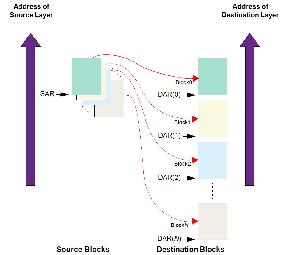
Multi-block DMA transfer with source address auto-reloaded and linked list destination address
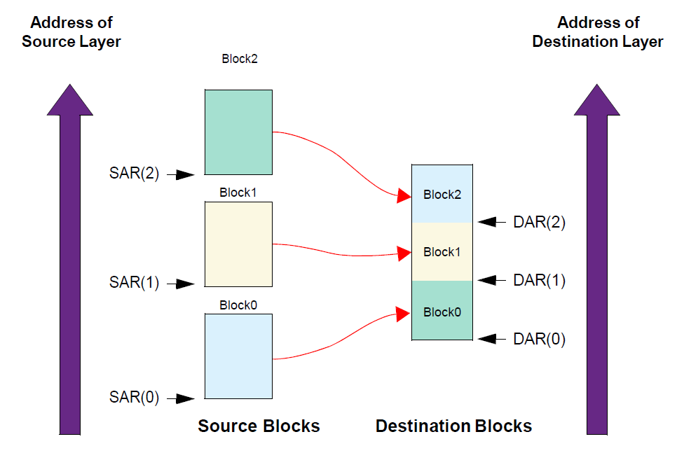
Multi-block DMA transfer with linked list source address and contiguous destination address
Multi-block DMA transfer with linked address for source and destination
Address Increment Type
Source Address Increment
There are two modes:
Increment: Indicates whether to increment the source address on every source transfer. Incrementing is done for alignment to the next CTLx.SRC_TR_WIDTH boundary.
No change: If the device is fetching data from a source peripheral FIFO with a fixed address, then set this field to No change.
Destination Address Increment
There are two modes:
Increment: indicates whether to increment destination address on every destination transfer. Incrementing is done for alignment to the next CTLx.DST_TR_WIDTH boundary.
No change: If the device is writing data to a destination peripheral FIFO with a fixed address, then set this field to No change.
Real-time Status Acquisition
GDMA supports real-time acquisition of the current transmission source address, destination address and the data size that has been transmitted. Call the corresponding APIs to read.
Note
To get the amount of data that has been transferred, the block_ts must be greater than 768 at least, and cannot be read in an interrupt function; otherwise, the value obtained is always 0.
Interrupt Type
There are several supported interrupt types, which can be used independently or in combination.
Interrupt type |
Introduction |
|---|---|
block interrupt |
Triggered by the completion of a data block transfer |
transfer interrupt |
Occurs when all data blocks have been transferred |
error interrupt |
There was a transfer error |
Note
In multi-block, when the block in auto-reload mode is interrupted, the data will be transmitted after the interrupt processing function.
In linked list mode, the transfer-completed condition is that the pointer of the last data block pointing to the next data block is null.
In linked list mode, when the block interruption comes, the data will still continue to be transmitted.
Secure
To start secure transfer, users need to configure the security channel control bit in the register.
Access for master interface and slave interface are secure when the secure bit is set.
Secure channel can only be configured in secure world, and secure channel can access secure memory and non-secure memory.
Non-secure channel can only access non-secure memory.
PGDMA_InitTypeDef->SecureTransfer = 1;
Suspend and Abort
GDMA supports channel suspend resume and termination.
To suspend a channel, just configure CFGx.CH_SUSP, but there is no guarantee that the current data transaction is completed. Combined with CFGx.INACTIVE, the channel can be safely paused without losing data.
To resume data transmission after suspension, clear CFGx.CH_SUSP.
To terminate data transfer, CFGx.INACTIVE must be continuously polled until this bit is set to 1, then the data transfer can be aborted.
Note
The following is situation that channels is inactive:
CFGx.INACTIVEcan only be activated after Memory has been written, and then canceled.The data of peripheral is 4 bytes, but the FIFO of DMAC is only 2 bytes. There is no writing at this time and
CFGx.INACTIVEis activated directly.
Priority
GDMA supports two kinds of channel priority:
Software: the priority of each channel can be configured in the
CFGx.CH_PRIOR. The valid value is 0 ~ (DMAC_NUM_CHANNELS-1), where 0 is the highest priority value and (DMAC_NUM_CHANNELS-1) is the lowest priority value.Hardware: if two channel requests have the same software priority level, or if no software priority is configured, the channel with the lower number takes priority over the channel with the higher number. For example, channel 2 takes priority over channel 4.
Cache
When DMA slave type is memory, you need to pay attention to cache operation. DCache_CleanInvalidate() should be called every time before DMA transmission starts.
The following steps should be added when executing DMA Rx/Tx.
Operation |
Step |
|---|---|
DMA Rx |
Note During GDMA transmission, it is forbidden to write or cache flush DST buffer. (Taking
u32 uart_recv_string_done(void * data)
{
   UNUSED(data);
   // To solve the cache consistency problem, DMA mode needs it
   DCache_Invalidate((u32)rx_buf, SRX_BUF_SZ);
   dma_free();
   rx_done = 1;
   return 0;
}
|
DMA Tx |
|
Aligning the buffer address with the cache line will reduce the problem of inconsistent cache and memory data, and details can be referred to Section Cache Consistency When Using DMA.
DMAC Demos
Single Block
Allocate a free channel
ch_num = GDMA_ChnlAlloc(gdma.index, (IRQ_FUN) Dma_memcpy_int, (u32)(&gdma), 3);
This function also includes the following operation:
Register IRQ handler if using interrupt mode
Enable NVIC interrupt
Register the GDMA channel to use
Configure the interrupt type
PGDMA_InitTypeDef->GDMA_IsrType = (TransferType | ErrType);
Configure interrupt handling function
Clear the pending interrupt in the interrupt processing function.
GDMA_ClearINT(0, PGDMA_InitTypeDef->GDMA_ChNum);
Configure transfer settings
PGDMA_InitTypeDef->GDMA_SrcMsize   = MsizeEight;
PGDMA_InitTypeDef->GDMA_SrcDataWidth = TrWidthFourBytes;
PGDMA_InitTypeDef->GDMA_DstMsize = MsizeEight;
PGDMA_InitTypeDef->GDMA_DstDataWidth = TrWidthFourBytes;
PGDMA_InitTypeDef->GDMA_BlockSize = DMA_CPY_LEN >> 2;
PGDMA_InitTypeDef->GDMA_DstInc = IncType; // if dst type is peripheral:no change
PGDMA_InitTypeDef->GDMA_SrcInc = IncType; // if src type is peripheral:no change
Configure hardware handshake interface if slave is peripheral
GDMA_InitStruct->GDMA_SrcHandshakeInterface= GDMA_HANDSHAKE_INTERFACE_AUDIO_RX;
or
GDMA_InitStruct->GDMA_DstHandshakeInterface = GDMA_HANDSHAKE_INTERFACE_AUDIO_TX;
Configure the transfer address
PGDMA_InitTypeDef->GDMA_SrcAddr = (u32)BDSrcTest;
PGDMA_InitTypeDef->GDMA_DstAddr = (u32)BDDstTest;
Program GDMA index, GDMA channel, data width, msize, transfer direction, address increment mode, hardware handshake interface, reload control, interrupt type, block size, multi-block configuration and the source and destination address using the
GDMA_Init()function.GDMA_Init(gdma.index, gdma.ch_num, PGDMA_InitTypeDef);
Clean and invalidate Cache
DCache_CleanInvalidate();
Enable GDMA channel
GDMA_Cmd(gdma.index, gdma.ch_num, ENABLE);
Multi-block
This example is SRC auto reload, compared with single block, multi-block is different in Step 2 to Step 4.
Allocate a free channel
ch_num = GDMA_ChnlAlloc(gdma.index, (IRQ_FUN) Dma_memcpy_int, (u32)(&gdma), 3);
This function also includes the following operation:
Register IRQ handler if use interrupt mode
Enable NVIC interrupt
Register the GDMA channel to use
Configure the interrupt type
PGDMA_InitTypeDef->GDMA_IsrType = (BlockType | TransferType | ErrType);
Configure interrupt handling function
Clear the interrupt.
GDMA_ClearINT(0, GDMA_InitStruct->GDMA_ChNum);
Clear the auto reload mode before the last block starts.
GDMA_ChCleanAutoReload(0, GDMA_InitStruct->GDMA_ChNum, CLEAN_RELOAD_SRC);
Configure transfer settings
PGDMA_InitTypeDef->GDMA_SrcMsize   = MsizeEight;
PGDMA_InitTypeDef->GDMA_SrcDataWidth = TrWidthFourBytes;
PGDMA_InitTypeDef->GDMA_DstMsize = MsizeEight;
PGDMA_InitTypeDef->GDMA_DstDataWidth = TrWidthFourBytes;
PGDMA_InitTypeDef->GDMA_BlockSize = DMA_CPY_LEN >> 2;
PGDMA_InitTypeDef->GDMA_DstInc = IncType; // If DST type is peripheral: no change
PGDMA_InitTypeDef->GDMA_SrcInc = IncType; // If SRC type is peripheral: no change
PGDMA_InitTypeDef->GDMA_ReloadSrc = 1;
PGDMA_InitTypeDef->GDMA_ReloadDst = 0;
Configure hardware handshake interface if slave is peripheral.
GDMA_InitStruct->GDMA_SrcHandshakeInterface= GDMA_HANDSHAKE_INTERFACE_AUDIO_RX;
or
GDMA_InitStruct->GDMA_DstHandshakeInterface = GDMA_HANDSHAKE_INTERFACE_AUDIO_TX;
Configure the transfer address
PGDMA_InitTypeDef->GDMA_SrcAddr = (u32)BDSrcTest;
PGDMA_InitTypeDef->GDMA_DstAddr = (u32)BDDstTest;
Program GDMA index, GDMA channel, data width, Msize, transfer direction, address increment mode, hardware handshake interface, reload control, interrupt type, block size, multi-block configuration and the source and destination address using the
GDMA_Init()function.GDMA_Init(gdma.index, gdma.ch_num, PGDMA_InitTypeDef);
Clean and invalidate Cache
DCache_CleanInvalidate();
Enable GDMA channel
GDMA_Cmd(gdma.index, gdma.ch_num, ENABLE);