MP Image
MP image is used for chip Calibration and Test during mass production.
To meet diverse user requirements, the SDK provides two types of MP image: Shrink MP Image and Expand MP Image. Their differences are as follows:
Image Type |
Size |
Download Area |
Lifetime |
Description |
|---|---|---|---|---|
Shrink |
Small |
Flash |
Retained after power-off |
|
RAM |
Lost after power-off |
|
||
Expand |
Large |
Flash |
Retained after power-off |
|
Image Type |
Size |
Download Area |
Lifetime |
Description |
|---|---|---|---|---|
Expand |
Large |
Flash |
Retained after power-off |
|
Image Type |
Size |
Download Area |
Lifetime |
Description |
|---|---|---|---|---|
Expand |
Large |
Flash |
Retained after power-off |
|
Image Type |
Size |
Download Area |
Lifetime |
Description |
|---|---|---|---|---|
Shrink |
Small |
Flash |
Retained after power-off |
|
Expand |
Large |
Flash |
Retained after power-off |
|
Generate Image
Below are the steps to generate MP image:
Refer to Configuring SDK (menuconfig) to modify the project configuration.
Enter
CONFIG Mass Production, checkEnable MP > MP Mode > shrinkto set the MP type to shrink.Return to the
MENUCONFIG FOR Generalpage, checkCONFIG WIFI > Enable Wifito enable Wi-Fi.Return to the
MENUCONFIG FOR Generalpage, checkCONFIG BT > Enable BTto enable Bluetooth.Save and exit.
Refer to Building Code to build the project.
Note
The generated MP image xxx_app_mp.bin is located in {SDK}\amebaxxx_gcc_project.
Refer to Configuring SDK (menuconfig) to modify the project configuration.
Enter
CONFIG Mass Production, checkEnable MP > MP Mode > expandto set the MP type to expand.Return to the
MENUCONFIG FOR Generalpage, checkCONFIG WIFI > Enable Wifito enable Wi-Fi.Return to the
MENUCONFIG FOR Generalpage, checkCONFIG BT > Enable BTto enable Bluetooth.Save and exit.
Refer to Building Code to build the project.
Note
The generated MP image xxx_app_mp.bin is located in {SDK}\amebaxxx_gcc_project.
Combine and Download Image
Typically, MP image does not include application code, it needs to be combined with the application image to switch to the customer application after completing Calibration and Test .
Below are the steps to combine image:
Prepare
km4_boot_all.bin,km0_km4_app_mp.bin, andkm0_km4_app.bin.Use Image Tool to combine the images.
Open the Generate tab and input the paths of the three files mentioned above.
Set the Offset according to the Flash Layout in
{SDK}\component\soc\usrcfg\amebadplus\ameba_flashcfg.c.const FlashLayoutInfo_TypeDef Flash_Layout[] = { /*Region_Type, [StartAddr, EndAddr] */ {IMG_BOOT, 0x08000000, 0x08013FFF}, //Boot Manifest(4K) + KM4 Bootloader(76K) //Users should modify below according to their own memory {IMG_APP_OTA1, 0x08014000, 0x081F3FFF}, //Certificate(4K) + Manifest(4K) + KM4 Application OTA1 + Manifest(4K) + RDP IMG OTA1 {IMG_BOOT_OTA2, 0x08200000, 0x08213FFF}, //Boot Manifest(4K) + KM4 Bootloader(76K) OTA {IMG_APP_OTA2, 0x08214000, 0x083DCFFF}, //Certificate(4K) + Manifest(4K) + KM4 Application OTA2 + Manifest(4K) + RDP IMG OTA2 {FTL, 0x083DD000, 0x083DFFFF}, //FTL for BT(>=12K), The start offset of flash pages which is allocated to FTL physical map. {VFS1, 0x083E0000, 0x083FFFFF}, //VFS region 1 (128K) {VFS2, 0xFFFFFFFF, 0xFFFFFFFF}, //VFS region 2 {USER, 0xFFFFFFFF, 0xFFFFFFFF}, //reserve for user /* End */ {0xFF, 0xFFFFFFFF, 0xFFFFFFFF}, };
Click the Generate button at the bottom to generate the combined image
Image_All.bin.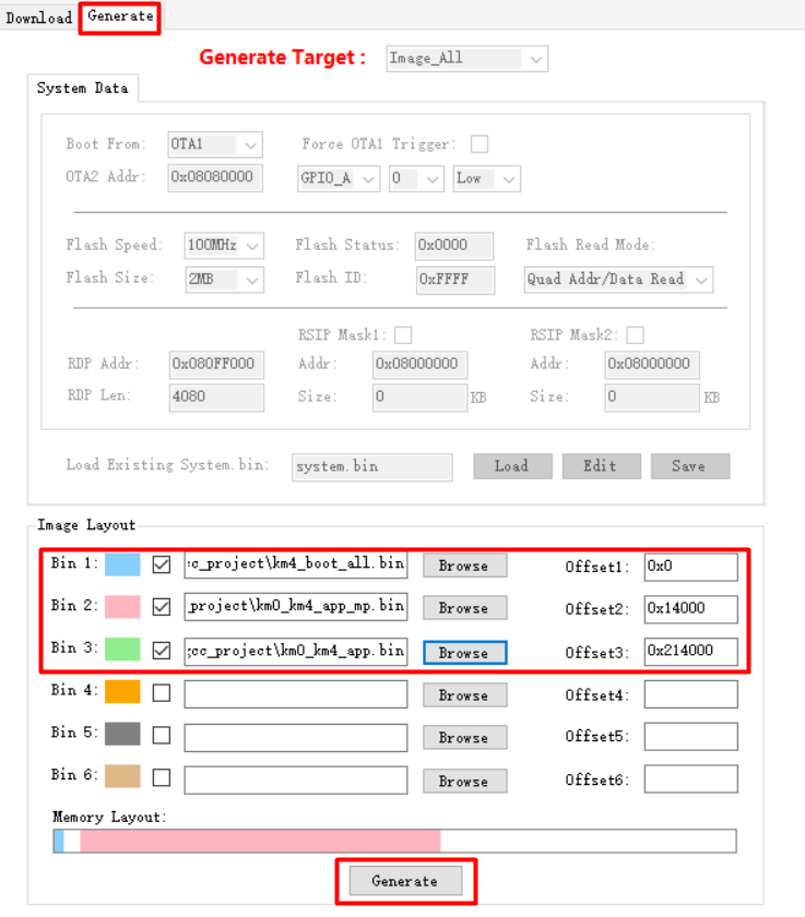
Use Image Tool or 1-N MP Tool to download
Image_All.binto the chip.
Note
km0_km4_app.bin is the customer application image, and km4_boot_all.bin is the bootloader image, both located in {SDK}\amebadplus_gcc_project. Typically, the MP image shares the same bootloader with the application image.
Prepare
km4_boot_all.bin,kr4_km4_app_mp.bin, andkr4_km4_app.bin.Use Image Tool to combine the images.
Open the Generate tab and input the paths of the three files mentioned above.
Set the Offset according to the Flash Layout in
{SDK}\component\soc\usrcfg\amebalite\ameba_flashcfg.c.
FlashLayoutInfo_TypeDef Flash_Layout[] = {
    /*Region_Type,      [StartAddr,     EndAddr]                */
    {IMG_BOOT,          0x08000000, 0x08013FFF}, //Boot Manifest(4K) + KM4 Bootloader(76K)
    //Users should modify below according to their own memory
    {IMG_APP_OTA1, 0x08014000, 0x081F3FFF}, //Certificate(4K) + Manifest(4K) + KR4 & KM4 Application OTA1 + Manifest(4K) + RDP IMG OTA1

    {IMG_BOOT_OTA2, 0x08200000, 0x08213FFF}, //Boot Manifest(4K) + KM4 Bootloader(76K) OTA
    {IMG_APP_OTA2, 0x08214000, 0x083DCFFF}, //Certificate(4K) + Manifest(4K) + KR4 & KM4 Application OTA2 + Manifest(4K) + RDP IMG OTA2
    {FTL,                       0x083DD000, 0x083DFFFF}, //FTL for BT(>=12K), The start offset of flash pages which is allocated to FTL physical map.
    {VFS1,                      0x083E0000, 0x083FFFFF}, //VFS region 1 (128K)
    {IMG_DSP,           0x08400000, 0x086FFFFF}, //Manifest(4K) + DSP IMG, only one DSP region in layout
    {VFS2,                      0xFFFFFFFF, 0xFFFFFFFF}, //VFS region 2
    {USER,                      0xFFFFFFFF, 0xFFFFFFFF}, //reserve for user

    /* End */
    {0xFF,                      0xFFFFFFFF, 0xFFFFFFFF},
};
Click the Generate button at the bottom to generate the combined image
Image_All.bin.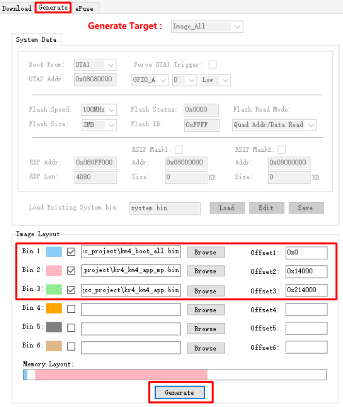
Use Image Tool or 1-N MP Tool to download
Image_All.binto the chip.
Note
kr4_km4_app.bin is the customer application image, and km4_boot_all.bin is the bootloader image, both located in {SDK}\amebalite_gcc_project. Typically, the MP image shares the same bootloader with the application image.
Prepare
km4_boot_all.bin,km0_km4_ca32_app_mp.bin, andkm0_km4_ca32_app.bin.Use Image Tool to combine the images.
Open the Generate tab and input the paths of the three files mentioned above.
Set the Offset according to the Flash Layout in
{SDK}\component\soc\usrcfg\amebasmart\ameba_flashcfg.c.
/*
* @brif     Nor Flash layout is set according to Nor Flash Layout in User Manual
*  In each entry, the first item is flash regoin type, the second item is start address, the second item is end address */
FlashLayoutInfo_TypeDef Flash_Layout_Nor[] = {
    /*Region_Type,          [StartAddr,     EndAddr]                */
    {IMG_BOOT,                      0x08000000, 0x0801FFFF}, //Boot Manifest(4K) + KM4 Bootloader(124K)
    //Users should modify below according to their own memory
    {IMG_APP_OTA1,          0x08020000, 0x082FFFFF}, //Certificate(4K) + Manifest(4K) + KR4 & KM4 Application OTA1 + Manifest(4K) + RDP IMG OTA1
    // + AP IMG OTA1
    {IMG_BOOT_OTA2,         0x08300000, 0x0833FFFF}, //Boot Manifest(4K) + KM4 Bootloader(252K) OTA
    {IMG_APP_OTA2,          0x08340000, 0x0861FFFF}, //Certificate(4K) + Manifest(4K) + KR4 & KM4 Application OTA2 + Manifest(4K) + RDP IMG OTA2
    // + AP IMG OTA2
    {FTL,                           0x08620000, 0x08622FFF}, //FTL for BT(>=12K), The start offset of flash pages which is allocated to FTL physical map.
    {VFS1,                          0x08623000, 0x08642FFF}, //VFS region 1 (128K)
    {VFS2,                          0xFFFFFFFF, 0xFFFFFFFF}, //VFS region 2
    {USER,                          0xFFFFFFFF, 0xFFFFFFFF}, //reserve for user
    /* End */
    {0xFF,                          0xFFFFFFFF, 0xFFFFFFFF},
};
Click the Generate button at the bottom to generate the combined image
Image_All.bin.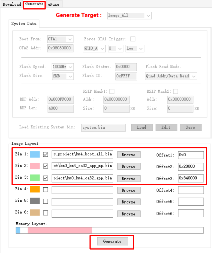
Use Image Tool or 1-N MP Tool to download
Image_All.binto the chip.
Note
km0_km4_ca32_app.bin is the customer application image, and km4_boot_all.bin is the bootloader image, both located in {SDK}\amebasmart_gcc_project. Typically, the MP image shares the same bootloader with the application image.
Boot and Switch Image
After downloading
Image_All.binto the chip, reboot the chip. By default, it will run OTA1 (MP image).[BOOT-I] IMG2 BOOT from OTA 1, Version: 1.1 ... [WLAN-A] Init WIFI [WLAN-A] MP driver
Execute Calibration and Test . After completion, enter AT+OTACLEAR to clear the signature of the current image to invalidate the MP image.
Reboot the chip. It will run OTA2 (customer application image).
[BOOT-I] IMG2 BOOT from OTA 2, Version: 1.1
Calibration and Test
Wi-Fi and Bluetooth Calibration
There are two methods for calibrating chip’s Wi-Fi and Bluetooth: Standard Calibration and Fast Calibration. Both methods apply to different test conditions and are included in Shrink MP Image and Expand MP Image.
Calibration Method |
Cost |
Test Duration |
Accuracy |
Description |
|---|---|---|---|---|
Standard Calibration |
High |
Long |
High |
Uses professional test equipment for wired tests. |
Fast Calibration |
Low |
Short |
Low |
Uses Realtek-provided signal board for wireless tests. |
Note
Only RTL8721Dx supports Fast Calibration.
Standard Calibration
Refer to WS_RTL8721DA_RTL8721DC_RTL8721DG_MP_FLOW.pdf for details.
Refer to WS_RTL8720E_RTL8726E_MP_FLOW.pdf for details.
Refer to WS_RTL8720E_RTL8726E_MP_FLOW.pdf for details.
Refer to WS_RTL8730E_MP_FLOW.pdf for details.
Fast Calibration
Refer to WS_RTL8721DA_RTL8721DC_RTL8721DG_Fast_MP_FLOW.pdf for details.
Custom Test
Besides Wi-Fi and Bluetooth calibration, MP image supports adding custom tests.
For example, to test GPIO functions of specific pins, implement using APIs defined in {SDK}\component\soc\amebaxxx\hal\src\gpio_api.c. Others like {SDK}\component\soc\amebaxxx\hal\src\serial_api.c and {SDK}\component\soc\amebaxxx\hal\src\spi_api.c apply to UART and SPI function test.
Note
For adding custom AT commands in SDK, refer to AT Commands.
User Data
Besides image, user data can be optionally downloaded to chips during mass production.
Different download methods exist based on data type:
For common data such as audio files, it is recommended to refer to Combine and Download Image to combine it with image into a single file and download to the chip.
If each chip’s data is different (e.g., product license), it’s unsuitable to combine with image.
It is recommended to customize AT commands in the MP image to receive data files via LOGUART and write to Flash. After the MP image runs, the host computer transfers the special data to the chip.
Note
The APIs defined in {SDK}\component\soc\amebaxxx\hal\src\flash_api.c support this functionality.